Design Notes
Design Notes
Overall rationale
Design Considerations
When designing Pipettin Bot, we kept the following considerations in mind:
- Cost: Use inexpensive and readily available components to make the parts, tools, and materials accessible to everyone.
- Complexity: Make Pipettin Bot easy to assemble and use, even for users with no prior experience in mechanics or electronics.
- Accuracy and precision: Create micropipettes that can pipette accurately and precisely, even at small volumes.
- Flexibility: Ensure that Pipettin Bot can integrate well with other open labware projects.
Features
To achieve these design goals, we incorporated the following features into Pipettin Bot:
- Modular design: This makes it easy to assemble, disassemble, and customize Pipettin Bot for specific needs.
- Open source software: This allows anyone to contribute to the development and improvement of Pipettin Bot.
- 3D-printed parts: This reduces the cost of Pipettin Bot.
- Off-the-shelf parts: We used inexpensive and readily available parts to achieve this, keeping the cost and complexity of Pipettin Bot low. Some components, such as the stepper motors and microcontrollers, were purchased off-the-shelf to reduce the cost and complexity of the bot.
- Easy-to-use interface: This makes Pipettin Bot accessible to users with no prior experience in the field.
Design Flow chart
When designing something new:
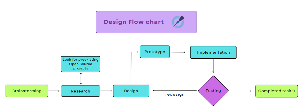
1. Brainstorming
- What do we want to do and for what?
- Which is our goal?
- What specific problems or challenges are we trying to solve?
2. Research
- Identify existing open source robots that meet our requirements or are similar.
- Evaluate the pros and cons of each robot.
- Take into considerations the working principles while looking for ideas.
- Keep in mind the interaction of that piece with the rest of the robot.
- Identify the key features and requirements of the new part.
3. Design
- Create sketches and schematics.
- Use CAD software to model our robot and simulate its assembly and operation.
4. Prototype
- 3D print our prototype.
5. Implementation
- Integrate your new design with the robot.
6. Testing
- Test the prototype to ensure that it meets our requirements.
- Gather feedback from coworkers
If the prototype meets your needs, then the task is completed. Otherwise, make necessary changes to the robot's design and start again at step 3. Redesign!
Info
Always remember to document every step of the way when ceating a new aspect of the project. Failure documentation is especially important, as it can help you to avoid making the same mistakes again :).
Design choices
Design decisions were made based on cost and functionality as mentioned above. We wanted the parts of Pipettin Bot to be easy to machine and cheaper than other alternatives, so we decided to make most of them 3D printed.
For example, when assembling the structural frame, we noticed that the profiles rotated. To solve this problem, we 3D printed plastic locks with small tabs that fit into slots on the profiles. We also added four 3D printed articulated legs to the structure to elevate the robot from the surface and ensure a stable and level position. This solutions are both effective and cheap.
For the baseplate, on the other hand, we used a 3D printed regularly spaced, square grid of 6 mm holes, which we call "curb" modules. These modules are used to generate guides on the workspace that can be used to align objects relative to the machine's coordinates easily and consistently. Once again, they are cheap to produce.
For the motion system, we noticed that the first version of the robot (which employed template rods as axes to facilitate its movements) exhibited excessive wobbling, which hindered precise movement. To solve this we came up with the idea of using 20x40 V profiles. These profiles are also cheaper an easier to buy than rods in Argentina.
While there are many expensive and high-quality pipetting robots on the market, there is a lack of affordable DIY options. This is why we prioritized affordability over aesthetics in the design of Pipettin Bot, even though we believe it is cute <3
We are always looking for ways to improve Pipettin Bot without sacrificing its functionality. However, failures can happen, so it is important to regularly maintain certain essential parts of the robot that may be damaged during use. To learn more about how to do this, please follow the Maintenance Guide.
Working principles
Baseplate
The baseplate plays a crucial role in providing stability and precision for the Pipetting Bot. Its design utilizes the principles of Maxwell kinematic coupling to achieve this.
You can learn more about this mechanism in the knogledgebase page.
V-Slot System and Maxwell Coupling
The baseplate incorporates a series of V-slotted extrusions, which are aluminum profiles with a V-shaped groove running along their length. These extrusions mate with corresponding wheels or rollers on the other components of the bot, such as the gantry and carriages. This V-shaped geometry creates six points of contact between the baseplate and the other components.
These six contact points, spread across different planes, restrict the movement of the connected parts in all directions except one. This ensures that the components can only move along their designated axes, maintaining precise positioning and preventing any unwanted rotations or translations.
Info
More information available here.
Micropipette
To seal the pipette we decided to to use o-rings.
O-rings
O-rings are a critical component to keeping out or sealing in fluid or gas. They are usually a donut-shaped ring made of rubber and fit within a special gland or groove to assist in the sealing process.
So how do O-rings work?
In low-pressure situations, the gland or groove forces the O-ring to compress, and that's what creates the seal.
In high pressure systems, the O-ring is forced onto the gap by high pressures and fills in the gap where the gas or fluid is trying to escape. The high pressure creates an efficient and tighter seal, preventing fluids or gas from passing around the O-ring. If you need to seal your application, we have engineers here on staff ready to help you with your gland or groove dimensions. with your gland or groove dimensions.
-*For more information regarding this topic visit here.
Motors
Pipettin bot uses stepper motors to achieve controlled motion.
Open-loop control and stepper motors
Open-loop control and stepper motors are commonly used in CNC for their simplicity, cost-effectiveness, and ability to provide accurate and repeatable motion control required for precise tasks. Pipetting bots typically perform operations at relatively low speeds and require accurate positioning, making this a suitable choice for the application.
- For more information regarding this topic visit here.
Tool-changer
Our toolchanger is based on Jubilee's Toolchanger, but we implement some crucial changes. It's placed on the bottom end of the Z-axis, and it's attached with some screws to the 20x40 V profile.
REL: Remote Elastic Lock
Jubilee's Tolchanger (an also ours) is based on the concept of 'REL', short for "Remote Elastic Lock".
In short, it means that:
- It admits mis-alignment (± 1 to 2 mm).
- The motor isn't mounted on the toolchanger (is remote).
- Constant locking torque ('elastic').
In our Tool-changer version, a spring keeps the tool locked in place, so we have a 'normal tension' (reminiscent of a 'normal closed' switch) . When we want to park the tool, we just go to the toolparking and release the tool by pulling from a sheathed wire (i.e. a bike brake cable) and some pulleys connected with belts (like an 'inverse' bicycle brake, if that helps).
- For further information regarding this topic visit the tool-changer design notes available here.
Pipettin Bots parts: Design notes
- Baseplate design notes
- Structural Frame design
- Backpanel design
- Motion system design
- Tool-changer design
- Electronics design
- Micropipettes design
Overview of internal modules, public APIs, or interoperability endpoints
Main repo, including all components as submodules: https://gitlab.com/open-la/pipettin-bot
Submodules:
- WebUI: Pipettin Writer is the web app for creating protocols and operating the Pippetin Bot. It provides an easy setup process of workspaces and protocols, and it can be used to send commands directly to the robot. Running the project is simple and requires minimal to no coding knowledge.
- Piper: Piper is one of the robots controller / commander. It is a software component that is responsible for processing commands from the user and generating G-code instructions to control the Pipettin Bot. The controller also communicates with Klipper, a firmware platform, to execute the G-code instructions.
- Newt API: Newt is a Python module that provides API and data schema validation, as well as object generation for the Pipettin project. Convenience functions to generate and validate JSON representations of pipetting objects (i.e. protocols, steps, labware, etc.). Also includes JSON schemas for them.
- Mix: Mix is a protocol generator for Pipettin Bot. It is a Python script that can be used to generate Pipettin Bot protocols for a variety of tasks, such as dispensing liquids, mixing liquids, and transferring liquids. Mix can be used to automate and optimize pipetting steps in a number of ways.
Follow software for more information on Pipettin Bots controller, APIs, database and web app.