Development
This page is missing:
- Setup details for development or testing.
- Detailed overview of the hardware modules and software. In progress
- Specifications of the internal and external hardware and software interfaces. In progress
- List of standards that apply.
- Tutorials and examples for how to get started or adding new modules.
Roadmapping Open Automation
See: https://gitlab.com/open-la/pipettin-bot/-/issues/96

Development Flow
How we process to develop something new for the project?
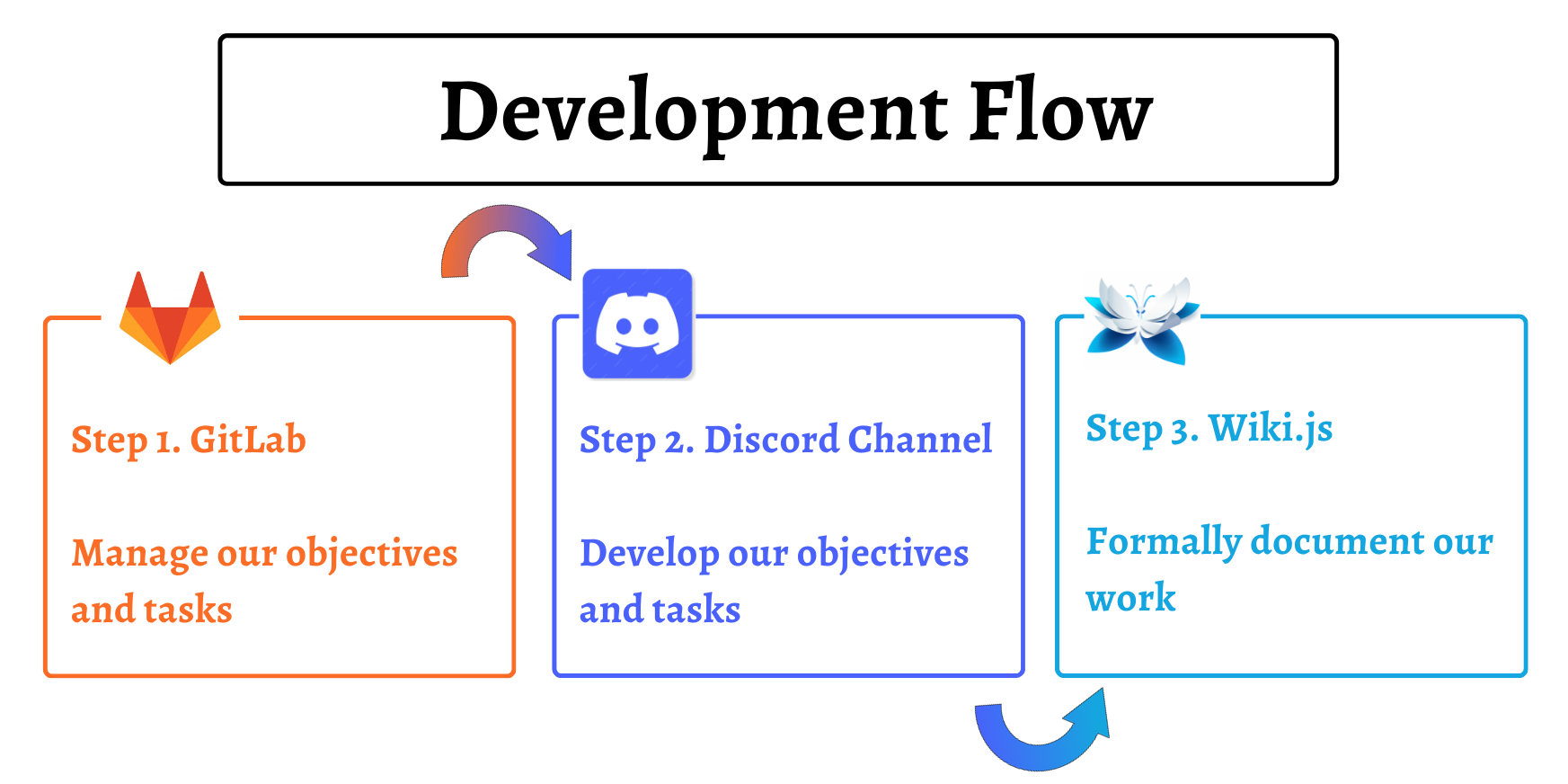
1. Task management with GitLab Issues
We manage our tasks using GitLab Issue Boards, where we set objectives, identify areas for improvement, and track pending work. We customize issues with tags to identify which part of the project they are related to, and we usually try to link related ones together.
Tasks should be atomic and clearly defined, while larger tasks should be split into smaller ones. This helps to keep track of progress and make useful to-do lists.
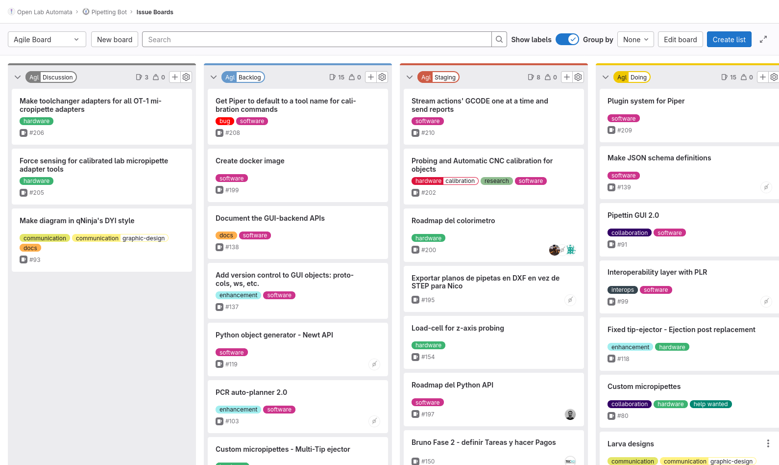
We organize our Issue Board with different lists, related to the "maturity" of the issue:
- Discussion → New ideas and tasks, in a gaseous phase. Useful as a to-do list, and for brainstorming.
- Backlog → Tasks that have a mature definition and will be carried out, but are not urgent yet.
- Staging → Prioritary tasks that are well defiend, and ready to be addressed.
- Doing → Tasks that are currently being worked on. This is where the actual development of the task takes place, including writing daily logs and generating content for the documentation.
- Feedback → Tasks that have been completed and are ready for review. This could be from other team members, users, etc. and the task could go back to a previous phase.
- Documentation → This stage is for creating documentation for the completed task after review. Tasks are only fully completed after they are documented in the published documentation.
- Done → Tasks that have been completed and documented.
To learn more about Gitlab Issue Boards, read their official documentation.
2. Development discussion at Discord
Once a GitLab issue exists for the task, we create a Discord thread where its development must be logged. This is effectively the objective's "log book". In this way, we can always check on each other, and participate in open development.
When working on a task, progress must be logged immediately in the the corresponding thread of our Discord server. We standardize this procedure with a daily log template, which must be copy-pasted and filled-out. We encourage the use of multi-media content for documentation (e.g. videos, photos, even audio messages).
Organization of the server
Our discord server is divided in many channels were you can find all the information regarding our project. The ones we use the most are "Pipettin Bot development" and "Contributions & Support".
Pipettin Bot Development forum:
- Documentation: Specification of what information should the wiki pages contain and where that information belongs.
- Tools: Discussions of tools that Pipettin Bot can support.
- Mechanics: Overall discussion of each hardware module of the project.
- Electronics: Installation of software. Software modules. Firmware configuration, etc.
- Protocols: Protocols with application in molecular biology.
- GUI: Discussion of new features of bugs the of the graphical user interface: Pipettin Writer
- Controller API: Development of a Python module for a project, which forms an "API" to program protocols, Newt.
- Resin printer: Tests and printer configuration for 3D printed resin parts of Pipettin Bot.
This is a good place to get feedback from your team and to brainstorm ideas. This also allows anyone who wants to access the most specific documentation of what the development process was like or understand why decisions were made regarding a specific topic.
Contributions & Support forum:
- Support forum: Place to provide assistance by resolving any issues one may encounter. By creating a post we can address the issue.
- Beginners corner: Place to provide assistance for beginners in automation.
- Feedback: Place for people to provide feedback on any aspect of the robot.
- Suggestions: Place to make suggestions to improve any aspect of the robot
- Development: General development discussion
- Documentation: Contributions made by people regarding documentation.
Anyone willing to contribute to the project, ask questions, or solve issues they enocunter is encouraged to chat with us!
Daily Development Log Template
When working on a task or objective on Discord we use what we call "Daily Development Log Template" to record our progress, once for each task we worked on throught a particular day.
It is divided in a few sections:
- Day's objective: What do we want to achieve today?
- Participants: Who worked on what?
- Results: What did we actually accomplish?
- Next steps: What will we do next?
- Documentation: What documentation was produced?
The goal of using this template is to make it easier to search for information, track our progress, get feedback from others, and see how close we are to our goals. It allows others to interact with our development journey.
Proper docuemntation, however, is not meant to live in this "chat" format. It must be digested and formatted into a wiki page, approximately every 10 days. It should not be stretched any longer, because otherwise one would forget many important details, as time passes.
The development logs are the main source of content for the real documentation, which we will discuss next.
3. Document our work
Here is where our project's documentation lives. While working on an objective, we also start to document the outcomes on the wiki. Thanks to the daily logs on our discord channels, this task is not as tedious as it may sound.
Once a GitLab issue exists for the task, we must also create a dedicated documentation page in the wiki. There is a technical documentation template for you to copy and paste into a new page, and fill it out as you work. The template also helps you structure and delimit your work more clearly.
Daily logs should be digested and re-formated into wiki format every 10 days.
The better the daily logs, the easier this becomes!
The main documentation allows people who want to dive into Pipettin Bot to do it easily. On one hand, they have a place where they can read about the project, and other places where they can read about it's development (discord channels, gitlab issues, etc.). With this system we aim to ensure that the reader has all the information available, for and easier and better understanding of our project.
Technical Documentation Template
To accomplish the above, we use what we call a "Technical Documentarion Template". This template is used to create and work on a documentation entry, for each new development objective that is defined.
How to use it:
- Copy the template file to an appropriate location in the documentation folder.
- Rename and edit the copy, replacing the default heading, and deleting the header (after reading all of it of course).
- Progressively add content to each section, using your lab notes as a source, every 7-10 days (adjust the interval to match your pace).
- Sections that do not apply to the relevant development objective should be adapted, skipped, or removed (in this order).
4. Test and evaluate our work
This step is one of the most important steps in our development journey. This process allows us to verify the accuracy and applicability of our output and documentation. This can consist of software or hardware testing, and also documentation testing.
For example, if we want to test a step-by-step guide on how to build a specific part of the bot, we will read the guide, follow its steps, and ask others to do the same if possible. This process helps us to ensure that no steps were skipped and that the information is accurate.
Tip
Writing good instructions is harder than you think! Take this into account.
Another example is testing that the output of the development task actually works, and integrates correctly with the rest of the project, as it should. This task is not optional. If the output does not interact with other parts as intended, then the task is not complete.
Development tools
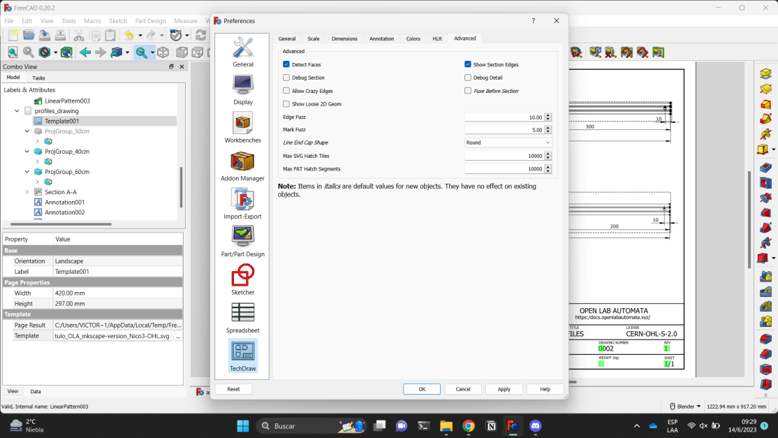
FreeCAD Software
We use FreeCAD version 0.20.1 to 3D model the Pipettin Bot's parts. It is a free and open-source parametric CAD modeler that can be used for a wide range of engineering tasks, including mechanical engineering, product design, architecture, finite element analysis, and 3D printing. It is licensed under the LGPL License.
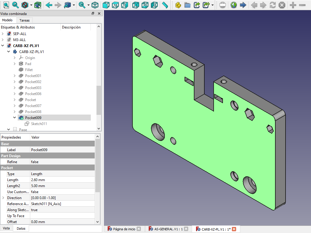
Info
Example of a FreeCAD file and its parameters. Information regarding how to model in FreeCAD is available here
Technical Drawing
We make drawings with FreeCAD's TechDraw workbench: https://wiki.freecad.org/TechDraw_Workbench
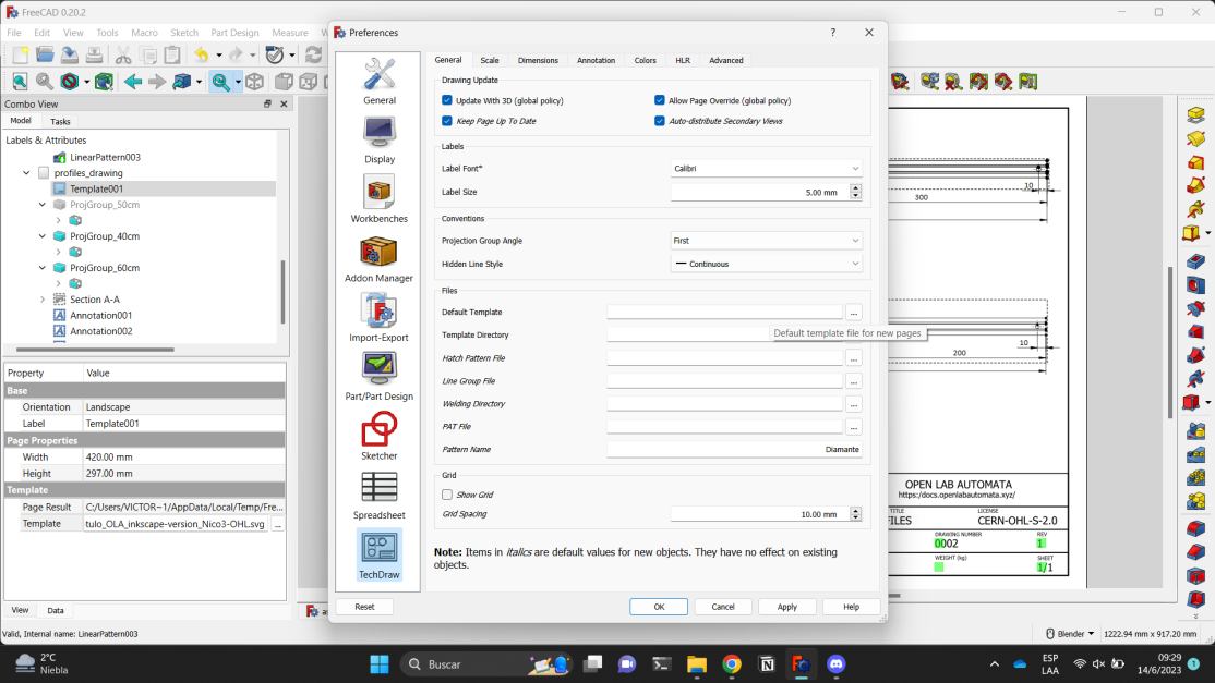
We use a common TechDraw template for the project's drawings: TechDraw Template
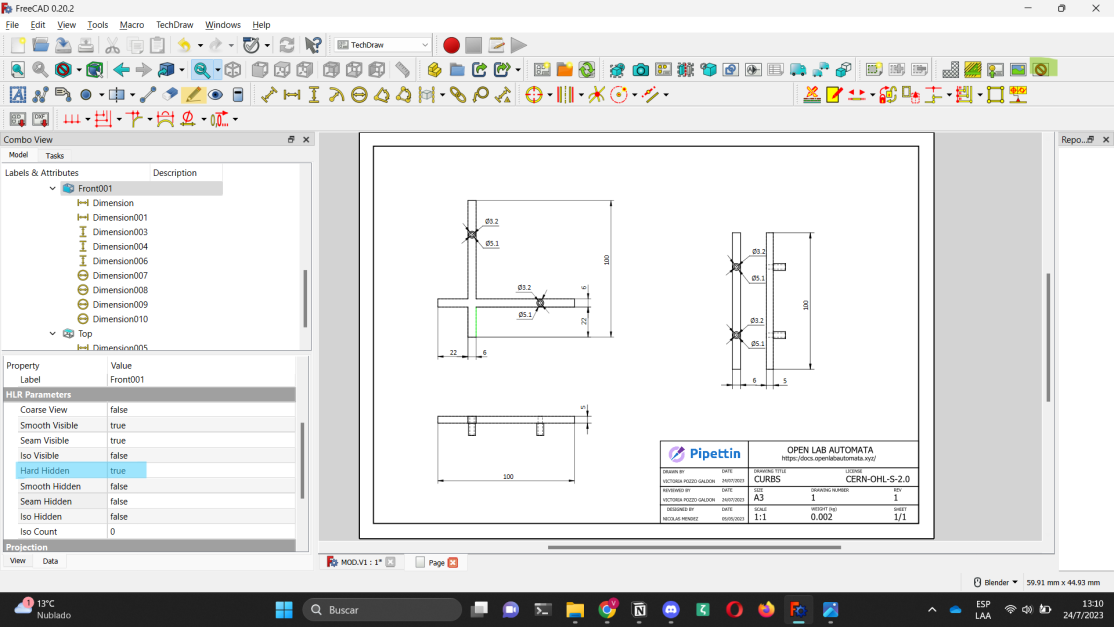
The template includes relevant information for each drawing, such as the project logo, drawing title, license, size, drawing number, measurements, and so on. Technical drawing templates help us create accurate and good-looking technical drawings.
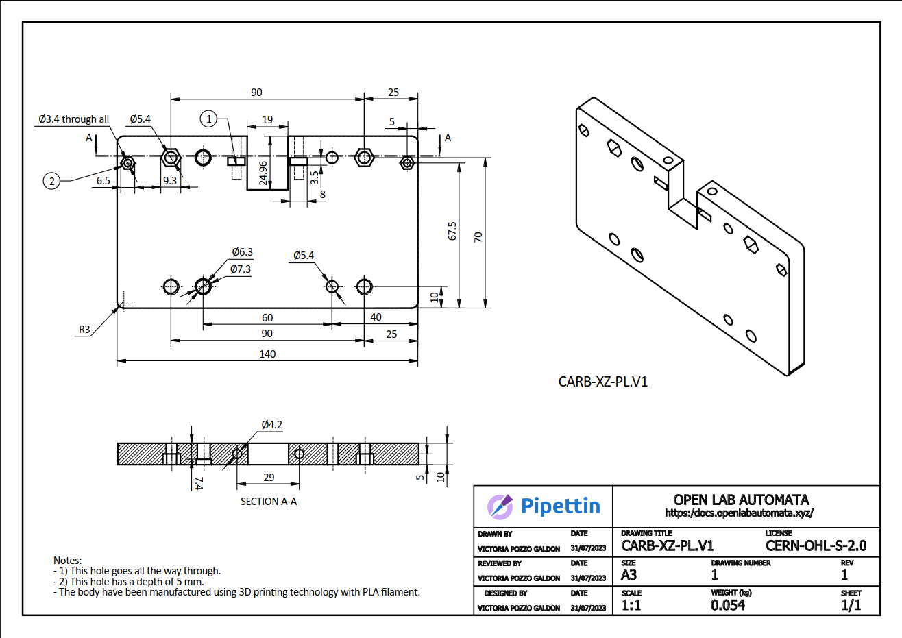
Example of a technical drawing
The sketches and technical drawing templates were created using the ISO 9001 quality management standards.
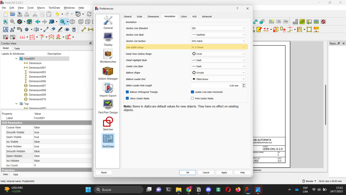
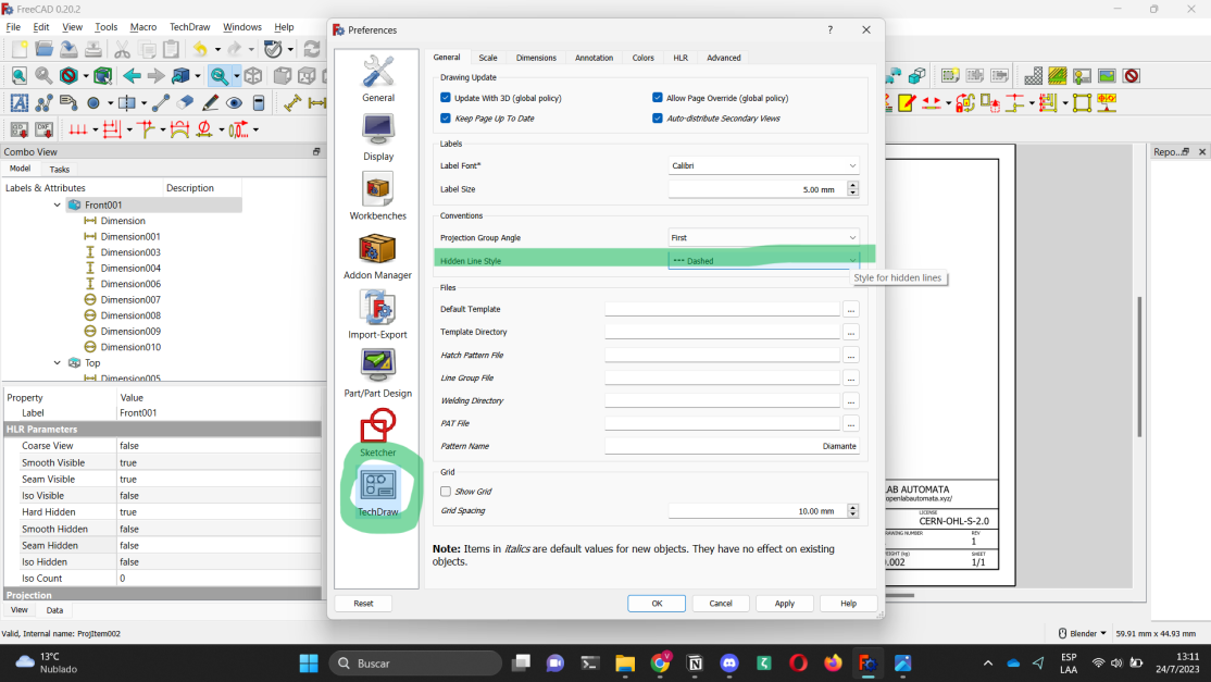
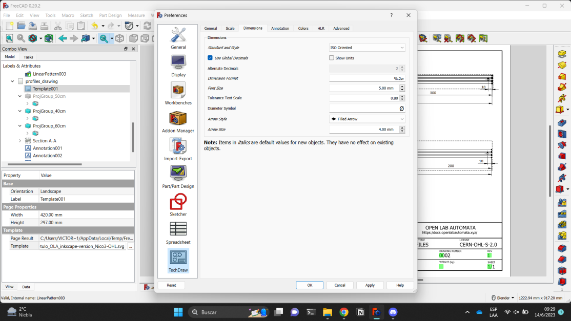
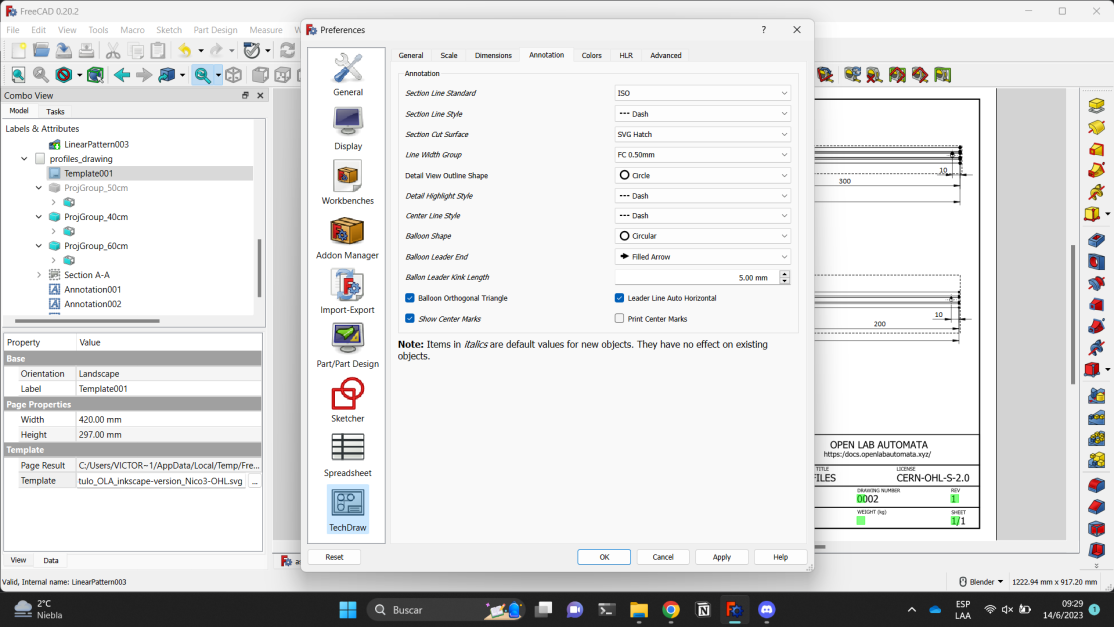
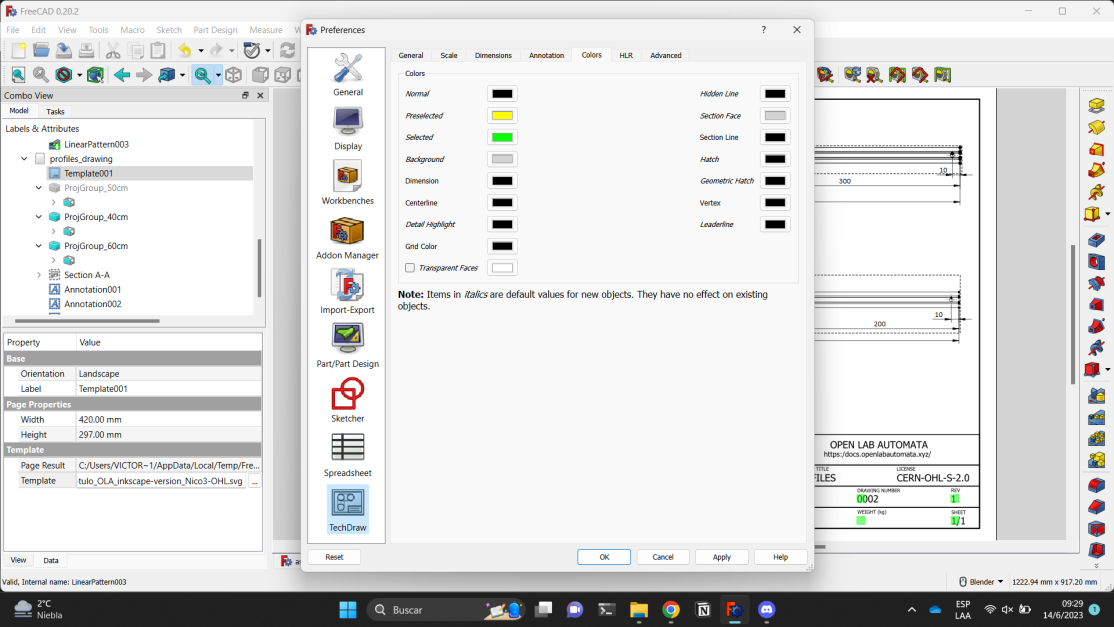
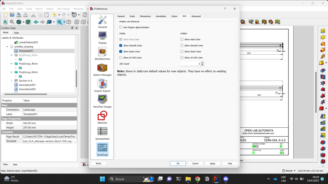
There are several parameters in TechDraw which can be adjusted:
- Line thickness
0.7(Line width group). - Show hidden edges as dotted lines (Hidden line style).
- To activate the visualization you have to access manually (blue: Hard hidden).
- Some useful tools:
- Hide edges (yellow: Hide edges): With this tool we can remove edges that have remained on the bodies, resulting from revolutions, etc.
- Print view (green: Print view): with this tool we can 'hide' all the annoying extra objects to have a clearer vision, without the need to export as pdf, as shown in the third image.
More screenshots:
Information regarding how to prepare technical drawing is available here
Part labeling
Info
Part labeling scheme available here
Part labeling serves as a unique way to identify each part in the robot assembly.
On the part labeling scheme you will find each piece with a corresponding name. To name them, we based on:
- Jubilee's scheme: https://jubilee3d.com/index.php?title=Part_Numbers
- Other References: https://hackaday.com/2020/12/02/a-case-for-project-part-numbers/
Parts: [part id + params + version]
Assemblies: [AS + params + version]
- Part Id
It refers to a name that is generally unique to each piece. The name is assigned depending on the functions it performs.
- Params
It refers to the most important parameters of the piece, such as length, width, thread, the axis on which it is located, etc.
- Version
It refers to the final version that is used. This allows us to control new modifications that are made to the pieces, especially when collaborating with other groups who modify the pieces at their convenience and then share their version with the community.
Assemblies must begin with the prefix AS, to be able to identify it quickly, and end with the corresponding version. The parameters vary depending on the parts that make up the assembly.
When can part names change?
- The revision number is only modified when a "slight" modification is made to a part or assembly; this mean that the modification does not make it incompatible with the parts or assemblies it originally interacted with.
- Part/Assembly IDs are incremented only when the modification on the part or assembly introduces an incompatibility with the parts or assemblies it originally interacted with.
Note
The versions of parts do not necessarily correspond to the version of the robot
If you want to dive into Pipettin Bot's models visit here.
File formats
.FCStd
The FreeCAD Standard file format (.FCStd) is FreeCAD's main file format. It is a compound format, supports compression and embedding of different kinds of data. FCStd is a standard zip file containing one or more files in a specific structure. As such, it is possible to unpack a .FCStd file using a regular zip decompression tool.
Likewise, in FreeCAD you can import pieces in .STL format and save them in .FCStd format.
.STL
We also employ Stereolithography (.STL). It is a file format that is commonly used for 3D printing. STL files store the surface geometry of a 3D model as a series of triangles. This makes them very efficient to store and transmit, and it also makes them easy to slice into layers for 3D printing.
STL files are used by a wide variety of 3D printing software programs, including PrusaSlicer. Once an STL file has been sliced, it can be printed on a 3D printer to create a physical object.
.SVG
We also employ Scalable Vector Graphics (.SVG). It is a file format that is used to store vector images. Vector images are made up of mathematical equations, which means that they can be scaled to any size without losing quality. SVG files are often used for logos, icons, and other types of graphics that need to be scalable. SVG file formats were used to create our technical drawing templates.
It is the simplest format to export and import drawings in FreeCAD without suffering any drawing deformation.
.PDF
PDF is a universal file format that is used to print and share FreeCAD drawings on any platform, regardless of the operating system or software application.
.DXF
DXF files are used for laser cutting to provide the laser cutter with instructions on where to cut. DXF files contain vector graphics, which are made up of lines, curves, and shapes. The laser cutter uses this information to trace the path of the cut and produce a precise and accurate result.
To export a section of a FreeCAD model as a DXF file for laser cutting, you can follow these steps:
If you want to learn how to do so, please follow this link
In summary, you should:
- Switch to the Part Workbench.
- Create a section of the model using the Draft workbench's Section tool.
- Select the section and export it as a DXF file using the File > Export menu.
Once you have exported the DXF or SVG file, you can open it in your laser cutting software and cut out the section of the model.
.PNG
We use Inkscape to edit screenshots, images, and all other project-related visuals. Files are saved in .PNG format, as well as .JPG, .SVG, .PDF and .ZIP, among others.
Inkscape is a free and open-source vector graphics editor for GNU/Linux, Windows, and macOS. It offers a rich set of features and is widely used for both artistic and technical illustrations such as cartoons, clip art, logos, typography, diagramming, and flowcharting.
Inkscape uses vector graphics to allow for sharp printouts and renderings at unlimited resolution and is not bound to a fixed number of pixels like raster graphics.
Inkscape uses the standardized Scalable Vector Graphics (SVG) file format as its main format, which is supported by many other applications including web browsers.
Info
To learn how we model in Freecad, how to prepare technical drawings, how to download .FCStd files, modify them and so much more visit this page.
Setup details for development or testing
List of pages with development information:
- This page.
- The PC setup guide
Info
Under development!
Overview: hardware and software modules
Info
Under development!
Software: Code Flow
- Follow Software for an overview of Pipettin Bot's controller, database and web app.
Software overview for the Pipettin Bot project:

Protocol designer: Pipettin GUI
Source code for the Node.js GUI, written in the ReactJS framework (included as a submodule): https://gitlab.com/open-la/pipettin-gui
Get support or report errors by creating an issue here.
CNC Firmware: Klipper
The project has moved from GRBL to Klipper, but will stick to the Arduino UNO + CNC shield. Using more expensive boards is trivial with Klipper.
The directory contains general information relevant to the specific configuration for this project.
The full Klipper software stack has been forked and published over here:
- Meta-repo including all forks as submodules: https://gitlab.com/open-la-deps/forks/firmware/klipper-stack
- All forks, including Klipper: https://gitlab.com/open-la-deps/forks/
Protocol translators and GCODE senders
Piper
Piper are source files for the main python module, responsible for:
- Parsing "actions" of "mid-level" protocols from the GUI into GCODE (with a few "GCODE extensions").
- Operates the hardware, by sending GCODE to Klipper through Moonraker.
Newt
Newt is a small module (WIP) to generate JSON objects for workspaces, platforms, contents, and protocol steps.
The idea is to make JSON "schemas" for each kind of data.
Mix
Mix generates information to prepare solutions with fixed and variable components (i.e. different conditions), using hierarchical clustering.
It's purpose is to automate the generation of "shorter" preparation of solution variants (e.g. PCRs using one master mix, but several templates, or primers).
It needs Newt to generate "high-level" protocol steps which can be fed to the GUI.
Startup scripts: Systemd.units
systemd.units files to start/restart the:
- Node.js server.
- Robot driver module.
- Klipper software stack.
- Jupyter Lab server.
- GitBuilding documentation server.
Units for the Klipper stack are available at the meta repo: https://gitlab.com/open-la-deps/forks/firmware/klipper-stack
Hardware: Control Flow
Warning
Under development!
Hardware modules for the Pipettin Bot project:
To-Do: Hardware modules connections diagram assigned to electronics team
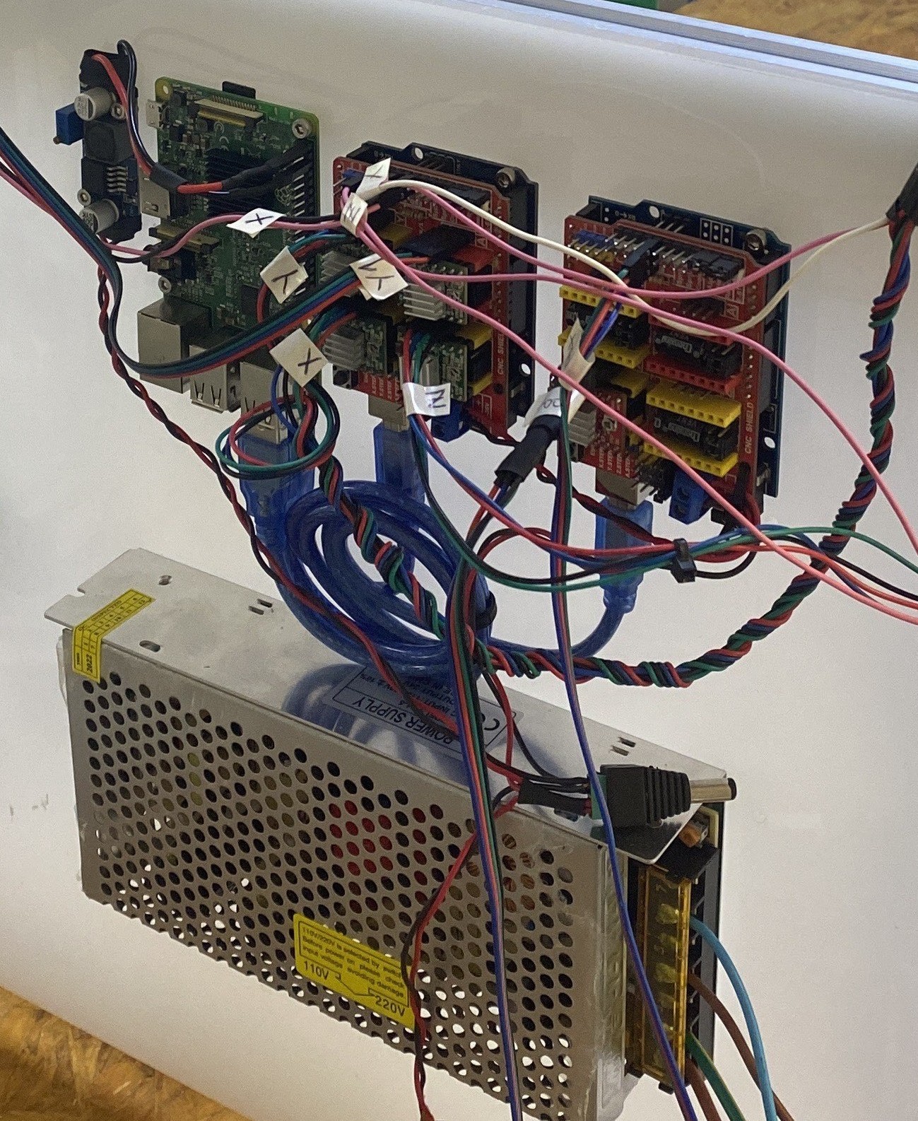
Electronics
-
Follow Control electronics and Main computer for an overview of Pipettin Bot's hardware modules.
-
Follow Electronics to learn how to assembly Pipettin's Bot electronics.
Mechanics
- Follow Mechanics for an overview of Pipettin Bot's mechanics parts.

The robot on the left is the previous version and the robot on the right is the current one (not updated).
Internal and external hardware and software interfaces
Hardware interfaces:
- USB: An interface for connecting peripheral devices to the computer, such as serial devices, keyboards, mice, etc.
- Ethernet (not used): A wired interface for connecting network devices to the computer.
- WiFi: A wireless interface for connecting network devices to the computer.
- Bluetooth (not used): A short-range wireless interface for communicating devices.
- GPIO (not used): A general-purpose input/output interface that allows microcontrollers to interact with the outside world.
Software interfaces:
- API (Application Programming Interface): A set of rules and specifications that allow two software programs to communicate with each other.
- The GUI's backend API.
- Newt (not ready).
- GUI (Graphical User Interface): A graphical interface that allows users to interact with a computer.
- CLI (Command-Line Interface): A text-based interface that allows users to interact with a computer.
Adding new modules
Warning
Under development! Not available yet.