Calibration
Note
Under development!
Warning
Content below is incomplete or missing. This page is missing, at least:
- Instructions to calibrate the robot's CNC axes, coordinate system.
- Instructions to calibrate new platforms, slots, tools, and the tool-changer.
- Instructions to calibrate micropipettes (volumetric and tip placement).
- Required skills and resources.
The following uses vocabulary for the old version of the tool-changer, and is incomplete. Though conceptually similar, it must be updated.
Preamble
This document contains instructions for calibrating components of the Pipettin Bot robot. Calibration involves adjusting parameters such that the robot's physical components are described accurately in software.
Requirements:
- A fully working machine (i.e. completed Assembly Guide).
- Access to the Joystick.
Motion system
Calibration procedures for the motion system.
XY range
Draft
This section is missing pictures and more detailed instructions. Possibly also unification with what has been done in the electronics setup guide.
As explained in the electronics setup guide, we must find a value for the position_max parameters in the [stepper_x] and [stepper_y] sections, such that the range of motion for the XY correctly matches the physical limits of the machine.
Prerequisites:
- The
[stepper_x]and[stepper_y]sections of the configuration file must have correct values for thedir_pin,step_pin, andendstop_pinparameters. - The headplate must be empty (no tools mounted to it), and no tools should be parked on the backpanel.
Procedure:
- Home the X and Y axes.
- Note the current (maximum) X and Y coordinates.
- Carefully move the X and Y axes to the opposite end of the range of motion, until they barely touch the physical limit.
- If you reach the preconfigured limit before hitting the physical limit, try sending an
M211 S0command, to temporarily disable klipper's motion limits, and keep going. - Otherwise, increase the value of
position_max(andposition_endstop) in the[stepper_x]and[stepper_y]sections to a reasonable amount, and start over.
- If you reach the preconfigured limit before hitting the physical limit, try sending an
- Note the current (minium) X and Y coordinates.
- Calculate the difference between the current and initial coordinates (ie.
max_X - min_Xandmax_Y - min_Y). This is the true range of the X and Y axes. - Use Mainsail's configuration editor to update the value of
position_maxin the[stepper_x]and[stepper_y]sections, setting them to the values calculated in the previous step. - Set
position_endstopto the same value.
Setting limits with the baseplate
In case you were wondering, you can also set the limits of the X and Y axes in reference to a particular location of the baseplate (instead of a hard limit on the robot).
This has the added benefit of making workspace coordinates relative to a known and fixed location of the baseplate. This in turn is useful for using the same workspace coordinates between different robots.
Wouldn't that be cool?
Z-axis Origin
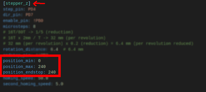
As explained in the electronics setup guide, it is critical that the headplate meets the baseplate at Z=0.
Because the Z-axis homes upwards, we must find a value for position_max such that the condition is satisfied.
Procedure:
- Home the Z-axis.
- Note the current Z coordinate as the top position.
- Carefully move the Z-axis downward, until it touches the surface of the baseplate.
- Note the current Z coordinate as the bottom position.
- Calculate the difference between the top and bottom position (ie.
top_Z - bottom_Z), this is the true range of the Z axis. - Use Mainsail's configuration editor to update the value of
position_maxin the[stepper_z]section, setting it to the value calculated in the previous step. - Set
position_endstopto the same value.
Remote actuator
The tool-changer's remote actuator does not require fine calibration, but it must work properly.
Rotation distance
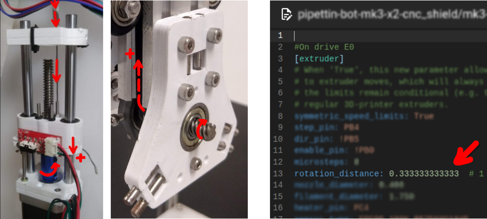
The tool-changing macros (defined in dynamic_macros.cfg files) expect the advance of the headplate's leadcrew to map directly to the E coordinate on GCODE commands.
To satisfy this requirement, the remote actuator is configured with a special "distance per revolution" parameter, that accounts for all intermediary mechanical elements (remote leadscrew, headplate GT2 pulley, and headplate leadscrew).
In this way, the rotation of the remote stepper motor is mapped to the linear advance of the leadscrew mounted on the headplate.
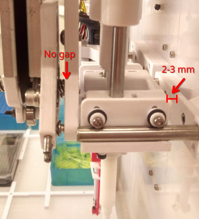
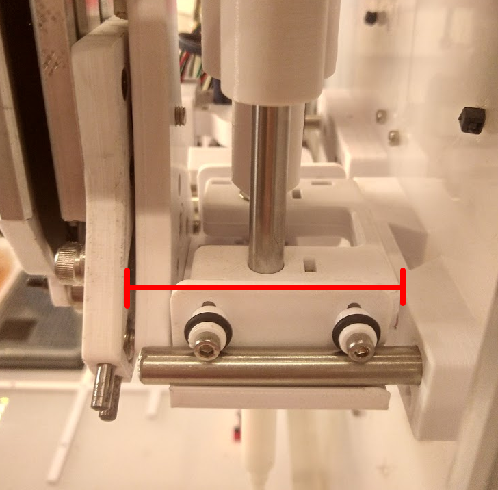
Total displacement
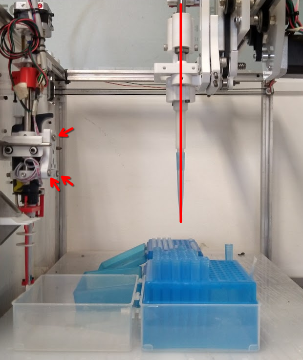
It is also important to limit the maximum range of the remote's motion, otherwise the GT2 belt that runs through the side of the Z-axis' profile might slide out and jam with the V-wheels.
In the image below the likely point for jamming is indicated in red:
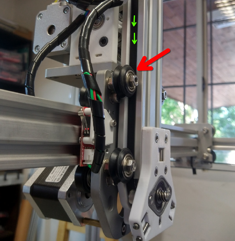
To prevent this, we will adjust the axis limits on the remote's [extruder] configuration section.
Procedure:
- Use the Mainsail UI to select the remote with
T0, home the remote withHOME_E0, and set the "Filament length" to 1 mm. - Manually present a tool to the headplate, and click on the
Retractbutton until the the tool is properly locked. - Inspect the tension of the cable just below its attachment to the top of the Z-axis.
- If it is still tense, continue moving the extruder using smaller increments, until the belt below starts to be loose or the physical limit is reached.
- If the cable is too loose, and the GT2 belt below slides out of the Z-axis' profile, click on
Extrudeto regain a bit of tension.
- Run the
GET POSITIONmacro and note the current position of the extruder axis. - Subtract this value from
position_maxin the[extruder]configuration section, and update it.- As a reference:
new_position_max = old_position_max - current_e_position - Do not increase
position_maxbeyond the physical limit of the remote actuator, or it will crash.
- As a reference:
- Update the final coordinate in the
PRIME_E0macro at the end of the file, such that itsG1points to a slightly lower coordinate thanposition_max(e.g. set it to around 6.5 or 6 if the maximum position was set to 7).
Corrections
If your motion system is not perfectly aligned, and this is almost always the case, you may want apply software corrections.
Conceptually, these involve making measurements with a tool, and comparing them with the expected motion.
There are two main types of corrections for the motion system's axes: mapping surface unevenness (mesh), and measuring skew on each axis.
WIP
Guide for axis skew and meshing corrections.
Issues:
- Mesh (WIP): https://gitlab.com/open-la/pipettin-bot/-/issues/359
- Skew (to-do): https://gitlab.com/open-la/pipettin-bot/-/issues/350
Height Mesh
Requirements:
- Z-axis probe tool (e.g. a accurate endstop mounted on the headplate, or Jubilee's awesome probe tool), configured in firmware and mounted on the toolhead.
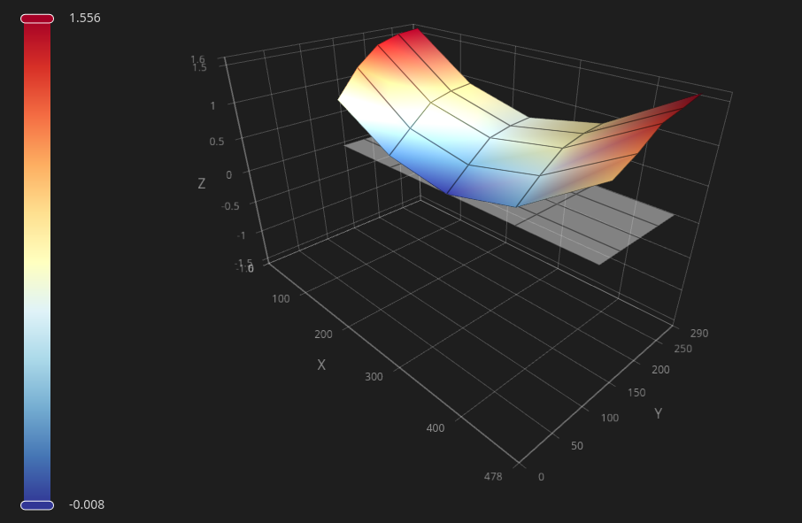
The firmware's "bed mesh" calibration can be used to correct for unevenness on the baseplate's surface.
The following image shows the result of a coarse measurement of the baseplate's surface using jubilee's probe tool. A maximum deviation of 1.5 mm can be observed, and revealing that the baseplate can be somewhat saddle-shaped instead of mostly flat or just tilted.
With these measurements, the mesh correction can automatically correct GCODE commands, in order to move the tool to the physically correct height relative to the baseplate's (curved) surface.
Procedure:
- Clear the baseplate of all objects (i.e. remove all platforms and curbs).
- Mount the probe tool on the headplate.
- Because nothing is yet calibrated, it may be simpler to do this by hand. Manually present the tool to the headplate, and use the ENGAGE and LOCK commands to lock it into position.
- If the tool is already calibrated, using the UI may be more comfortable.
- Use the firmware's mesh wirzard:
- Using Mainsail: https://docs.mainsail.xyz/overview/features/bed-mesh
- In depth explanation: https://www.klipper3d.org/Bed_Mesh.html
Here is a video overview of the process:
Skew
TO-DO
Figure out how to implement this, given that we cannot print a calibration object, because OLA not a 3D printer (by default at least).
Tool-changer
Tool-change Parameters
There are several key measurements that must be taken for each tool and its parking post:
- Docking coordinates: The XYZ coordinates of the headplate when aligned to parked tool (just "in front", and almost but not touching it).
- Main information used to pickup and park a tool.
- Parking post clearance: The Y-axis coordinate the parking posts when empty and with their tools parked.
- Used as an offset to avoid crashing the headplate with parked tools.
- Tool size: The length of a tool along the Y axis, measured from the front of the headplate once mounted (not considering the parking post).
- Used as an offset to avoid crashing a tool with parked tools.
A full set of tool-changing coordinates is required to define the sequence of pickup and parking movements for a tool and its parking post.
Tool-post parameters for parking and docking:
Parameter |
Description |
|---|---|
x |
X-coordinate of the toolhead when aligned and positioned just in front of a parked tool |
y |
Y-coordinate of the toolhead when aligned and positioned just in front of a parked tool |
z |
Z-coordinate of the toolhead when aligned and positioned just in front of a parked tool |
y_docking_closeup |
Distance from y up to which the toolhead moves quickly before final approach to a parked tool |
z_docking_offset |
Additional Z-axis offset during docking to compensate for alignment (in mm) |
y_parking_closeup |
Distance beyond y for initial parking position, fine-tuned for consistent docking |
z_parking_offset |
Additional Z-axis offset during parking to compensate for alignment (in mm) |
feedrate |
Speed of final docking and parking moves (in mm/min) |
Clearance parameters:
| Parameter | Description |
|---|---|
safe_y |
Distance along Y that the tool adds to the front of the toolhead |
safe_y_parked |
Minimum Y coordinate of the tool when properly parked |
safe_y_post |
Minimum Y coordinate of the parking post when it is empty |
The following diagram shows an overview of the main parameters:

If you measure and configure these parameters correctly, collisions will not happen.
Preparation
- Remove any tools from the tool-head, and place all tools on their corresponding parking posts.
- Open the Pipettin Writer UI and the Joystick (i.e. Mainsail) on a web browser.
Tool-plate alignment
Draft
Needs more content and testing.
By this procedure, any tilt between the tool and the headplate can be compensated.
- Manually load the tool on the headplate.
- Check if the tool is properly aligned with the rest of the machine.
- E.g. a pipette tool might be tilted relative to the XYZ axes.
- Check if the tool is tilted. If you observe this, remove the tool, adjust the screws on the toolplate (this will change the tool's tilt), and repeat steps 1-3.
Tool-wing alignment
Draft
Needs more content and testing.
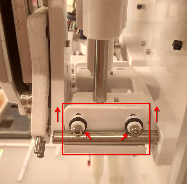
By this procedure, the parking wings on the tool will be placed correctly, to keep the tool from tilting when parked.
- Manually load the tool on the headplate.
- Slightly loosen the screws of the two support pins found on each the tool-wings.
- Manually move the tool to its parking post (we recommend disabling the steppers, and moving the machine by hand).
- Park it manually, and ensure that the o-rings on the supporting pins are in contact with the parking post's rods.
- Slide the tool-wings into slight contact with the rods, and re-tighten the screws of the support pins.
- Manually move the tool out of the post, and check that it does not offer much resistance to sliding.
- Remove the tool from the headplate, and place it back on the parking post.
Docking coordinates
Draft
Needs more content and testing.
To get the tool-change coordinates, first:
- Home the machine (
G28) and the remote actuator (HOME_E0). - Use the joystick to move the machine to the following locations, and take note of the coordinates at each step.
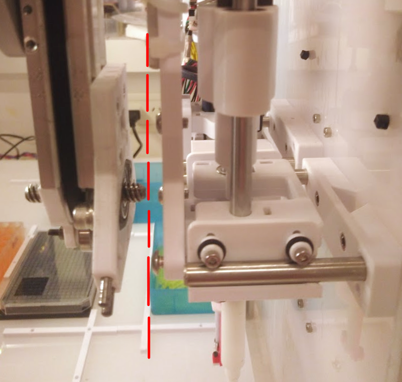
Stage 1: Post's Y-clearance
- Place the tool on its parking post, but not fully against the back of the post. Leave some room for the tool to slide in both directions (see images below).
- Move the headplate just in front of the a tool at its parking post, but clear of it in the X and Z directions.
- Write down the corresponding Y coordinate. This is
safe_y_parked.
Stage 2: tool_post coordinates
- Carefully move the headplate towards the tool, aligning and inserting the locking pin into the wedge-plate as far as it will without pushing the tool.
- Write down the X, Y, and Z coordinates. These are the
tool_post's XYZ coordinates.
Alignment tip
You can eyeball the alignment with a bit more ease by passing a screwdriver througt the headplate (as shown below), and moving it incrementally until its handle is level.
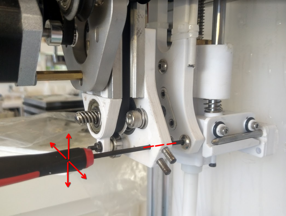
Critical
The tool and headplate must not yet touch, and must not bind at all.
Stage 3: safe_y
- Execute the GCODE commands for engaging (
ENGAGE) and locking (LOCK). - Slowly move the headplate away from the backpanel (now with the tool loaded) until it is clear of the parking post.
- Use a ruler or calipers to measure how much length the tool has added to the headplate over the Y axis. Write down this length as
safe_y.
Pickup moves must be smooth
If the tool does not slide cleanly and smootly out of the parking post, you may have to adjust the Z-coordinate, or revisit the tool-plate alignment or tool-wing alignment steps.
The tool might be tilted relative to the parking post and headplate, or the Z-coordinate may be incorrect.
Parking coordinates
Draft
Needs more content and testing.
The coordinates for parking are defined as offsets from the tool-post coordinates determined above.
- Slowly slide the tool back in the parking post, up to the Y-axis docking coordinate from the previous steps.
- Execute the GCODE commands for releasing (
UNLOCK) and clearing (CLEAR). The tool should now be free of the tool-head. - Compare the tool's location with the original tool-post location, determined during the first step of the docking calibration procedure.
- If the tool is not at the same location, set the
y_parking_closeupparameter equal to the observed difference (positive value if the tool should be closer to the post, or negative in the opposite case).
- If the tool is not at the same location, set the
Parking moves must be smooth
If during calibration the tool "parking" Z coordinate is different from the tool "pickup" coordinate, set this Z offset in the z_parking_offset slot of the tool's configuration.
If your machine is built well enough, the coordinates will not differ, and the offset should be set to zero.
Joystick test
Draft
Needs more content and testing.
Now that tool changing parameters are set, we can test the sequence to see if it will work correctly.
First test the tool-changing sequence by hand:
- Put the tool on its post, properly seated, and home the machine.
- Carefully move the headplate to the tool-post coordinates.
- Execute the GCODE commands for engaging (
ENGAGE) and locking (LOCK), and move the tool away form the post (e.g. 50 mm). - Move the tool back to the tool-post coordinates, and further by
y_parking_closeup. - Execute the GCODE commands for releasing (
UNLOCK) and clearing (CLEAR), and move the eadplate away form the post.
Save tool parameters
Draft
Needs more content and testing.
Update tool parameters with the new information, using the Pipettin Writer UI from a browser.
- Usa a browser to open the Pipettin Writer UI (found at port
3000, e.g. http://pipettin.local:3000/). - Open or create an empty workspace.
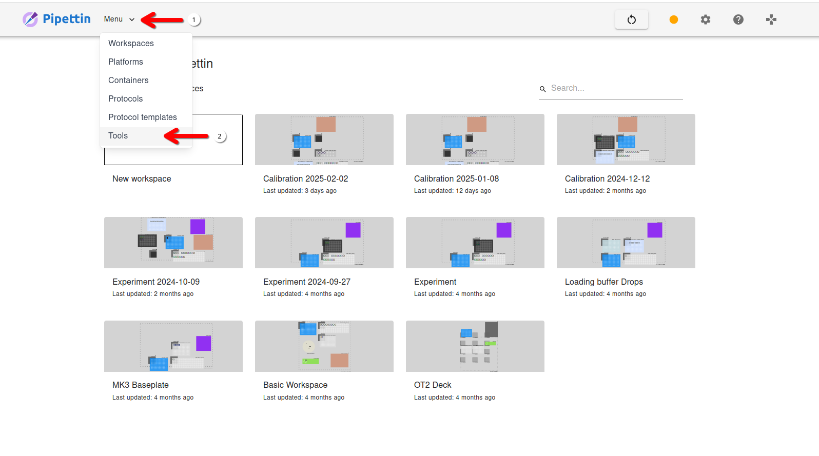
- Use the main menu (found at the top navbar) to open the list of tools.
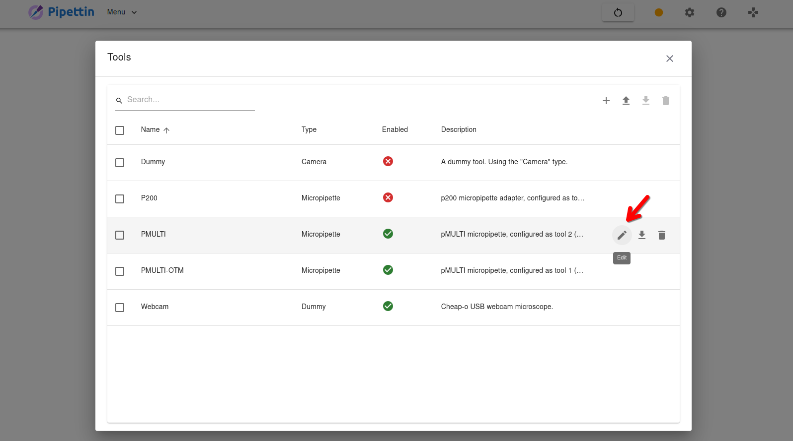
- Open (or create) a tool from the list, to edit its parameters.
- Use the provided text editor to edit the tool-changing parameters of the tool, which are shown in JSON format.
Editing tool parameters with the UI
You will need to open the tools menu on the Pipettin Writer UI. Click on "Menu" buttton on the left side of the navbar, and then select the "Tools" item from the drop-down list that appears.
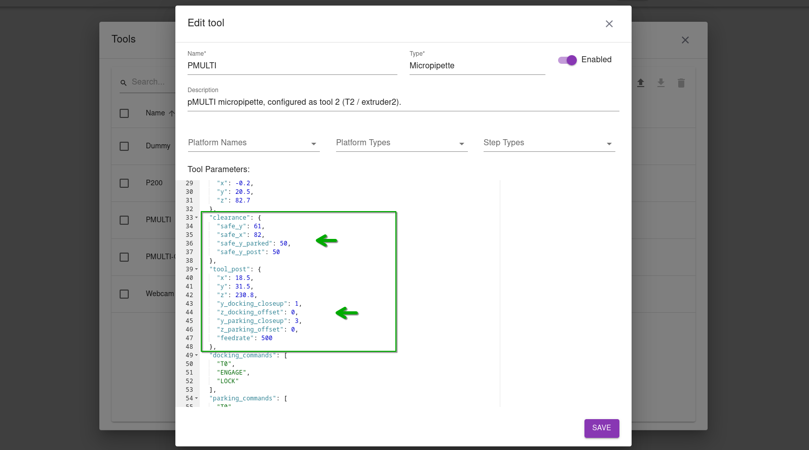
Update the default parameters for a pipette tool, shown here for reference:
  "clearance": {
    "safe_y": 61,
    "safe_y_parked": 50,
    "safe_y_post": 50
  },
  "tool_post": {
    "x": 18.5,
    "y": 31.5,
    "z": 230.8,
    "y_docking_closeup": 1,
    "z_docking_offset": 0,
    "y_parking_closeup": 3,
    "z_parking_offset": 0,
    "feedrate": 500
  },
Tool offset calibration
Draft
Needs more content and testing.
Determination of the XYZ offset between the tool and the headplate.
Tools may have an "active center" at a location away from the headplate. For instance, pipettes have tip holders that are found below and in front of the headplate, where tips are placed.
Preparation
To correctly determine the offsets for any given tool, you will need:
- A z-axis whose zero Z-position is at the point where the headplate touches the baseplate (as previously explained).
- The tool of interest, mounted on the headplate (e.g. a pipette).
For non-reference tools you will also need:
- A reference platform anchored to the workspace (e.g. a tip rack) with its platform definition in the database.
- A new workspace on the web UI.
Reference tool
Offset calculation procedure for the reference tool (i.e. the first one to be calibrated).
Warning
The Z-axis' origin (the zero coordinate) must map to the height at which the headplate touches the baseplate.
This can be achieved as explained above, in the Z-axis origin calibration procedure.
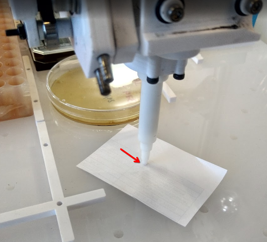
Procedure:
- Open Mainsail, and use the joystick to carefully move the tool downwards until it barely touches the baseplate (image below).
- Record the Z coordinate, this is the tool's Z offset.
- The remaining X and Y tool offsets will be set to an arbitrary number.
- This is arbitrary: you can set them to zero, but a more realistic number is preferred (e.g.
X=0,Y=25for a "pMulti" pipette tool).
- This is arbitrary: you can set them to zero, but a more realistic number is preferred (e.g.
- Save the XYZ tool offsets using the tool parameter editor (as shown above).
XY offsets of the first tool
The first tool that is calibrated will effectively be the reference tool, to which you will assign an arbitrary offset in X and Y.
This is the tool you'll use to calibrate the positions of the first platform item on a workspace, thus establishing the second useful relationship between the motion system and your labware (the first being the Z offset).
Other tools will have XY offsets ultimately related to the offsets on the reference tool, but they are independent. This means that even if the offsets on the reference tool change (e.g. due to accidents), no changes will be needed on other tools.
Reference platform
Up to this moment, the XY offsets between the baseplate and the motion system is undefined.
Because of it, we now need to use the reference tool to locate a reference platform (e.g. a well plate) on the virtual workspace. This will establish a link between the coordinates of the motion system and of the virtual workspace, for the first time.
Only then it becomes possible to calibrate the XY offsets of additional tools, by aligning the new tools to the reference platform.
Actually...
We could have, instead, mount a "probing plate" on the headplate and use it to redefine the origin of coordinates somewhere on the baseplate (by making a measurement and offseting the XY limits).
This would make positions of labware compatible between robots. We might implement this if a demand rises.
Procedure:
- Calibrate a platform item using the reference tool, as described below: platform position calibration.
- Calibrate additional tools, as explained below.
Additional tools
Offset calculation procedure for addtional (non-reference) tools:
Requirements
- Before moving on to new tools, you need to have calibrated a reference platform item using the reference tool.
- A reference platform must be placed on the workspace.
- Open Mainsail, and use the joystick to carefully move the tool downwards until it barely touches the workspace. The current Z coordinate is the tool's Z offset.
- Use the web UI to load the workspace where the reference platform is located.
- Click on the "Show Position" button of the workspace toolbar. The current position of the robot will be drawn on the workspace's area.
- Use the joystick to align the tool's center to the reference content (e.g. tip or well), such that the content is vertically aligned.
- To obtain the second tool's offset, calculate the difference between the macine's current XY position, and the XY position of the reference content on the workspace.
- Save the XYZ tool offsets using the tool parameter editor (as shown above).
Tool-change test
Draft
Needs more content and testing.
Now that tool changing parameters and tool offsets are set, we can test the full sequence with the web UI.
Precautions
Keep the "Emergency Stop" button at hand, to prevent damaging the machine in case the sequence fails due to incorrect coordinates, settings, or configuration.
Procedure:
- Open a workspace.
- Click on the "Show Position" button of the workspace toolbar. The current position of the robot will be drawn on the workspace's area.
- Select the tool using the workspace toolbar.
- Select a calibrated content on the workspace.
- Click on the "Go-to" button on the workspace toolbar.
- Wait for the headplate to pickup the tool and go to the content.
- Click on the "Park" button, and wait for the tool to be parked.
Workspace Calibration Guide
Warning
TO-DO
Prerequisites
This guide assumes that all of these things have been done:
- Fully assembled robot.
- Full software setup.
- You can access Pipettin Writer (the GUI) and Mainsail (the joystick for manual control).
If you have not yet done so, please follow the Assembly and Software & Electronics setup guides.
Deck position
Info
Due soon. Calibration of the position of the baseplate (i.e. its local origin of coordinates) relative to the machine's physical origin of coordinates (i.e. where the home position is located).
Platform position
Determination of a item's XY position on the workspace:
- Place the item on the workspace (e.g. a tip-rack or 96-well plate) against an anchor (a.k.a. platform curb).
- When calibrating tools, use a "reference" item to which you can precisely align the pipette's center (or tip if placed).
- Create a workspace, add the item to it, and add a content to the item (e.g. well or tip).
- The content will be used to determine the item's position on the workspace.
- Save the workspace.
- Open Mainsail, and carefully move the tool towards the object using the joystick, until it is exactly above the content you have chosen (e.g. well or tip).
- Click on the "Show Position" button of the workspace toolbar. The current position of the robot will be drawn on the workspace's area.
- Use the UI to move the virtual reference item, until its reference content is exactly below the cross marking the robot's position.
- Lock the item's position, and save the workspace.
What exactly is calibrated?
The position of the item on the workspace is calibrated, not the item's position on the baseplate.
This means that the item's position on the baseplate is unknown, but the relative position of the item to the machine's origin is known.
Additionaly, platforms are calibrated to their anchors (curbs) by the shape and size of their bottom surface, which actually comes into contact with the anchors. For example, some tip racks are wider near the top side, but the shape used to calibrate the platform to the anchors must be the bottom surface.
Platform curbs
TO-DO
Using platform anchors (aka. curbs) to repeatably place items on the workspace.
Once a platform is calibrated, it can be used to calibrate the position of anchors (curbs) on the workspace.
Procedure:
- Calibrate a platform item to an anchor (curb) as described above, using the reference tool.
- With the calibrated platform in place and locked, add an anchor to the workspace.
- Move the anchor to the platform's top-left corner.
- Lock the anchor's position.
- Save the workspace.
To test:
- Unlock the platform's position.
- Move the platform to a different position.
- Move the platform near the anchor, and check if it snaps to the same position where it was calibrated.
Generic
Generic instructions for calibrating items (e.g. for new types of platforms).
XY position
To do
Calibration of XY position.
Z position
Each platform has a top and bottom attribute, which we must calibrated with the reference tool.
To do
Calibration of Z position.
Examples
Tip Box
TO-DO
Calibration of tip boxes and tips.
Tube rack
TO-DO
Calibration of tube racks and tubes.
Pipette Calibration Guide
Calibration instructions for micropipette tools.
Tip-placement
Requirements:
- Calibrated tool changing and tool offsets.
- Calibrated tip-rack platform and calibrated workspace (with the tip-rack item in it).
- Known parameters for the tip holder's stages.
- Container definition for the tip (i.e. name and total length).
- The tip's container name should be added to the
tip_mapin the tool's parameters, associating it to the corresponding tip stage.
Procedure:
- Move over a tip (you can use the go-to command from the UI).
- Use Mainsail to carefully lower the tool, until its barely above the top of the tip. Write down the Z coordinate.
- Lower the tool carefully, until it barely fits the tip. Write down the Z coordinate.
- Take the difference between this value and the previous distance. This is a candidate for the
tip_fit_distanceparameter.
- Take the difference between this value and the previous distance. This is a candidate for the
- Raise the pipette and check if the tip is placed correctly (i.e. does it fall out easily? does it seal correctly?).
- If the fit was not tight enough, repeat the following until the tip fit is good:
- Repeat step 3.
- Lower the pieptte a bit more, pressing on the tip, and write down the Z coordinate.
- Repeat step 4.
- When the tip fit is good, take the difference between the last Z coordinate you wrote down, and the coordinate from step 2.
- This is the
total_sealing_distance.
- Move the tool upwards and then to the side of the tip rack.
- Lower the tool carefully until the tip touches the baseplate. Write down the Z coordinate.
- Take the difference between the tool's Z offset and this value. This is how much the tip adds to the tip holder.
- Take the difference between this value, and the tip's total length. This is the
total_fitting_distancefor the tip. - Subtract the tip stage's
z_offsetfromtotal_fitting_distance, and settip_fit_distanceto the resulting value value in the tool's parameters, at the corresponding tip stage's section. - Calculate
probe_extra_distby this formula and save it to the tool's parameters:probe_extra_dist = total_sealing_distance - total_fitting_distance
Tip-ejection post
This calibration procedure is useful for pipette tools that eject their tips by touching a "post", fixed to the back of the robot.
A micropipette tool might have several "tip stages" on its tip-holder, each with different tip sizes. Each stage has its own tip-ejection post, which means that we need to calibrate the tip-ejection post for each stage.
Stages are defined in the tool's definition, which can be edited using the "Tools menu" of the web UI.
We are now only interested in the coordinates of the tip-ejection post, which are found in the eject_post section of the tip stage's definition.
{
    "tip_stages": {
        "p200": {
            "eject_post": {
                "post_x": 237.4,
                "post_y": 48,
                "post_z_pre": 188,
                "post_z": 191,
                "eject_feed_rate": 600
            },
            "... other tip stage parameters ...": "..."
        },
        "... other tip stages ...": "..."
    },
    "... other pipette parameters ...": "..."
}
Calibration procedure:
- Place a tip on the tool manually (or automatically, as explained in the tip-placement section).
- Use Mainsail to move the tool towards the tip ejection post.
- Choose one tip stage to calibrate (e.g. 200 uL tip size), and carefully insert the tip holder between the ejector tabs of the corresponding tip size. The ejector's tabs should be located between the tip's top-end, and the beginning of the next stage of the tip holder (e.g. the one for 1000 uL tip sizes).
- Write down the XYZ coordinates of this position, these are the
post_x,post_y, andpost_z_prevalues. - Slowly move the pipette upwards until the tip is ejected. Write down the Z coordinates of this position, this is the
post_zvalue. - Save these values to the tool's parameters, in the corresponding tip stage's
eject_postsection. - Repeat for all other tip stages.
Alternative procedure (without tips):
- Use Mainsail to move the tool towards the tip ejection post.
- Choose one tip stage to calibrate (e.g. 200 uL tip size), and carefully insert the tip holder between the ejector tabs of the corresponding tip size. The ejector's tabs should be located just under the beginning of the next stage of the tip holder (e.g. the one for 1000 uL tip sizes).
- Write down the XYZ coordinates of this position.
- Slowly move the pipette upwards until the end of the tip stage is reached. Write down the Z coordinates of this position.
- Save these values to the tool's parameters, in the corresponding tip stage's
eject_postsection. - Repeat for all other tip stages.
Built-in ejectors
The micropipette adapter tools take advantage of the tip ejector built into traditional micropipettes.
Relevant tool parameters for a p200 micropipette adapter tool (single-channel, single-stage):
{
    "can_eject": true,
    "tip_stages": {
        "p200": {
            "tip_ejector": {
                "e_start": 22,
                "e_end": 27,
                "eject_feedrate": 200
            }
        }
    }
}
Loose fit
If the pipette is not correctly fastened to the adapter, it will become obvious notice at this step. As the tip ejector starts pressing on the tip to eject it, the pipette will change alingment, which can change again when a tip is placed, and cause collisions. To correct this, check that the fastener pieces holding the pipette are sufficiently tight.
Homing sequence
TO DO
Due soon. The following uses vocabulary for the old version of the tool-changer, and is incomplete. Though conceptually similar, it must be updated.
The initial state of a pipette is assumed to be at the first stop (when it's shaft is fully depressed, but not further than the start of the second stop).
From this position the pipette is ready to load volume.
What we need to find is the distance that the carriage must travel from the homing sensor (located at the top of the tool), to reach the second stop (but not further).
Check limit switches
Before doing this, make sure that your limit switches and stepper motors are correctly wired and configured. Otherwise things might crash into each other and some parts may be damaged.
If everything checks out, now it's time to tune the homing position, using the homing tool parameters.
  "homing": {
    "commands": [
      "T3",
      "HOME_EXTRUDER EXTRUDER=extruder3",
      "G90",
      "M82",
      "G1 E6 F6000; Move until the actuator touches the plunger."
    ],
    "commands.desc": "Homing commands, leaving the pipette at the maximum volume.",
    "travel_distance": 16,
    "travel_distance.desc": "Free travel distance after homing, to the lowest volume position."
  }
Procedure:
- Define a set of GCODE commands that will home the tool, and leave leaving the plunger at the maximum volume. Save these commands in the
commandstool parameter as a list. - Run the homing commands.
- In the case of pipette adapters, check that the actuator has reached the plunger. Otherwise, tune the homing commands to make it reach the plunger.
- Use
GET_POSITIONto obtain the initial coordinate of the pipette axis. - Move the plunger downwards until it touches the first stop.
- In the case of pipette adapters, check if the pipette's shaft has reached the first stop by grabbing the plunger from the sides and pushing it down. There should be no free travel left.
- Use
GET_POSITIONto obtain the new coordinate of the pipette axis. - The difference between the two coordinates is the
travel_distancevalue. - Save the
travel_distancevalue in the tool's parameters.
Seal verification
The pipette must be checked for proper sealing, throught its full range.
If liquid leaks out of the tip, the pipette's tip or o-ring may not be properly seated or aligned to the tip holder.
Leak check procedure:
- Home the tool, and move its plunger to the lowest position.
- Place a tip on the pipette, preferrably a p1000 tip.
- Aspirate water until the tip is full.
- Observe if any water leaks out of the tip, for up to two minutes.
- Some liquid may leak due to water evaporation inside the tip, but it should stop after a few seconds once it reaches equilibrium.
- If no leaks are observed, move the plunger downwards, to dispense some water (e.g. 10 uL).
- If leaks are observed, follow the instructions below.
- Repeat step 5 until the tip is empty.
Leak check troubleshooting:
- If liquid leaks out of the tip, the pipette's tip or o-ring are not seated properly.
- Fix Nº1: check that the tip is seated properly by removing it and reinserting it.
- Fix Nº2: disassemble the pipette, lokking out for:
- Misalignment in the plunger, relative to the tip holder.
- Improperly seated o-ring on the tip holder.
- Insufficient or missing lubrication on the plunger and o-ring surfaces.
Volumetric calibration
After assembly, each micropipette tool must be calibrated to ensure accurate volume measurements.
Automated calibration
We are working on this right now, stay tuned! 
Previous results
Old and messy calibration assays here and results here. Cleanup, update, and migrate.
Data available at: https://gitlab.com/open-la/pipette-calibrations
Requirements
Materials and tools:
- Micrometer tool or good calipers (0.01 mm, or better).
- Analytical / precision scale (0.1 microgram, or better). Note: a microgram is equivalent to a microliter at standard conditions (25°C, 1 atm).
- 1.5 mL micro tubes.
The micropipette tool must be:
- Correctly installed on its parking post, connected to the electronics, and configured (firmware-side), as per the assembly guides.
- Calibrated tool changing parameters and tool offsets.
- Calibrated workspace, contents, and containers with a tube rack for 1.5 mL tubes and p200 tip rack.
- Calibrated tip-placement and tip ejection parameters.
- All liquid handling corrections disabled (see procedure below).
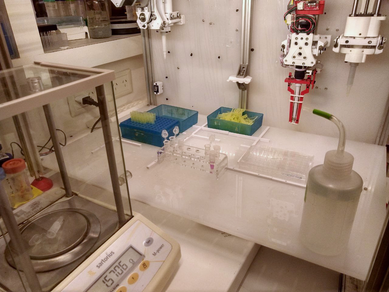
Tip: Calibration setup on the bench
If you are wondering how calibration looks like on the bench, here is a setup. Having the scale nearby is a real time saver. Taking fast measurements means that closing the lids is not as critical to prevent evaporation (although this can be accounted for with a control tube).
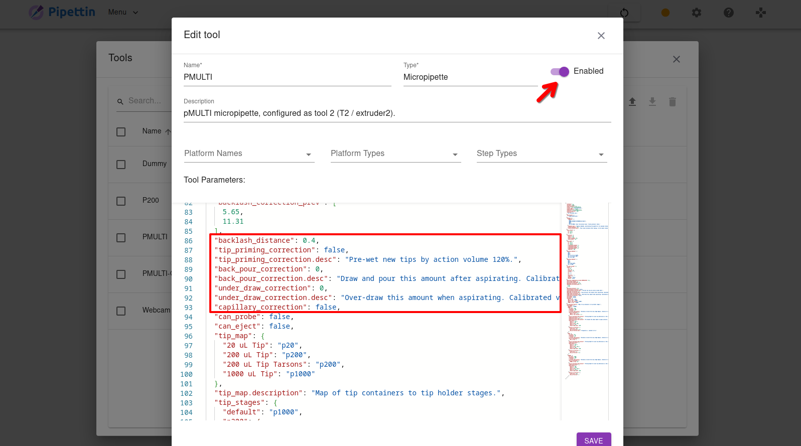
How to edit tool parameters
You will need to open the tools menu on the Pipettin Writer UI. Click on "Menu" buttton on the left side of the navbar, and then select the "Tools" item from the drop-down list that appears.
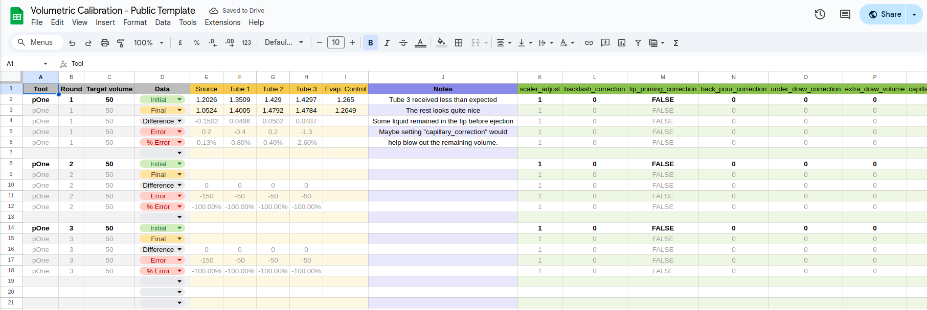
Calibration sheet template: https://docs.google.com/spreadsheets/d/1KZMEsKyrwZiT8NY0MaJC5Bq-OI-2W5kdStQT5__uxu4/edit?usp=sharing
- Make a copy of this "template" sheet to your Drive. You may find it useful.
- It is setup for 5 tubes: 1 source, 3 targets, and an evaporation control (not used by the robot).
Procedure
Main calibration procedure:
- Measure the diameter of the pipette shafts, and set the
shaft_diameterparameter. Setscaler_adjustto1. - Make sure that all of the above conditions are met. The correction parameters must be disabled by setting the following tool properties:
  "backlash_correction": 0,
  "scaler_adjust": 1,
  "capillary_correction": false,
  "extra_draw_volume": 0,
  "back_pour_correction": 0,
  "tip_priming_correction": false,
  "under_draw_correction": 0,
- Setup a protocol.
- Create a protocol with a single
TRANSFERstep, dispensing 30-50 uL serially in 3 or more tubes. - Measure the initial weight of all tubes, including the source tube (with sufficient water in it already).
- Create a protocol with a single
- Check for leaks.
- Run the protocol and measure the final weight of all tubes. Repeat a few times.
- If the pipette leaks, the first aspiration will be consistently under target, the last dispense will be under target at least as much, and the middle dispenses will be over target.
- To fix this inspect the piston assembly for mistakes and/or add lubricant (use a silicone-based grease for nitrile o-rings).
- Check for correct free travel.
- The
travel_distanceparameter under thehomingsection should match the free travel distance from the endstop exactly. - At this limit, the shaft should still have some free travel left, otherwise you'll see that the first aspirations are consistently under target.
- To check this, home the pipette manually (e.g. run
HOME_E2in Mainsail) and disable the steppers. Try rotating the motor manually, to check that the shaft has not hit its limit. - If there is too much or to little free travel:
- Update the parameter in Klipper's config for the homing macro (e.g.
[gcode_macro HOME_E2]) - Update
travel_distancein the tool's parameter to match it.
- Update the parameter in Klipper's config for the homing macro (e.g.
- The
- Set
backlash_correction.- Repeat the test protocol.
- If the above worked out nice, set
backlash_correctionvolume equal to the average difference (in microliters) between the first and second dispense moves. - Repeat a few more times to triple-check that there is now no difference between first and second dispense moves.
Tip: Eyeballing backlash
You can get an idea of the backlash by aspirating manually a small amount of water (e.g. 2uL), and then aspirating some air (e.g. 15 uL).
Move the pipette axis downwatds by 0.1 mm to dispense air, and check if the drop inside the tip starts moving downwards or not, and repeat. When it does, note the total displacement, and start moving upwards until the drop starts moving again.
This is good as an initial approximation. If too much is observed, try fixing issues in the mechanical assembly first.
A well assembled pipette will have little or no backlash. We have observed up to ~0.4 mm backlash distance with the cheapest actuators, which corresponds to a 12 uL backlash_correction error in a 6 mm shaft. This may sound terrible but can actually be corrected quite well.
- Set
extra_draw_volume.- Repeat the test protocol.
- Increase the value of
extra_draw_volumeif after the previous steps you observe that the initial aspiration and the last dispense are consistently below target, while the intermetiate dispenses are fine. - A symptom requiring this correction is that it runs out of volume on the last dispense, and blows a bit of air.
- This correction can be confounded by sealing issues (i.e. leaks), and can be distinguished from it by the correct intermetiate dispenses.
- Note: you can try setting
back_pour_correctioninstead, or both simultaneously (details below).
- Set
capillary_correction.- Repeat the test protocol.
- If the final dispense is consistently below the target because volume remains in the tip, but the initial aspiration is on target, set this parameter to
trueand tune thetension_correctionparameters. These parameters are related to the familiar "blow out" volume. - This correction is specific to each tip-stage, and more relevant to the smaller tips. Tune the
start_volandmax_correctionvalues by making small-volume serial dispenses that rely on the tip's tip. Look for the lowest volume where issues begin, and note the maximum magnitude of the deviation.
- Set additional correction parameters if needed. These are related to "wetting" tips.
- Set
back_pour_correctionif you observe that the liquid does not initially enter a new tip, and then suddenly does, distorting the results. The pipette might have trouble overcoming suface tension / wetting the tip, especially for small aspiration volumes. - Set
tip_priming_correctionif you need to pre-wet the tips before aspirating.- Serial pipetting with lots of dispenses make the sequence last longer, and increase the deviations introduced by liquid evaporation inside the tip.
- Set
under_draw_correctionif you need to consistently aspirate extra volume (extra_draw_volumeandback_pour_correctiononly apply to the first aspiration). - Set
scaler_adjust.- Repeat the measurements and estimate the overall deviation between the target volumes and actual volumes. Yuo may benefit from using larger volumes per dispense (e.g. 40-50 uL).
- For this calculation give greater importance to the intermediate dispenses (i.e. not to the initial aspiration or final dispense).
- For example, if dispenses and aspirations are in average 1.5% below their targets, set
scaler_adjust=1.015.
- Set
Congrats!
You've set-up and taken care of your machine.
Come back to these pages once in a while, specially if you start encountering any issues.
You may move on to the User Guide, or go back to the Home Page.
Troubleshooting
If you feel lost in calibration, this section may help.
Systematic error in serial dispenses
Serial dispenses have known issues in big brand robots. The Hamilton company, for instance, recommends discarding the first and last dispenses in a series.
There are however several sources of inaccuracy.
If you observe error across a serial dispense that is systematic (e.g. +1% in the second dispense, -1.5% on the third, 0.5% on the fourth, etc.) it is likely that the actuator has mechanical inaccuracies. Typical tolerances in a cheap 2mm-pitch leadscrew will account for errors in the 1% range.
This can be solved by using precision encoders on the rail, higher quality mechanical components, or by calibration and advanced software correction.
The pipettes.py tool module in Piper does not yet feature such software corrections, which might also be hard to measure without proper metrology equipment. We encourage you to use quality lead-screws and bearings, or switch to linear rails instead, if this becomes a problem for you.
You are welcome to reach out to us for help.
Lost steps during tool-changing
The machine's stepper motors can skip steps if they can't produce enough force (e.g. when ejecting or placing tips).
Possible solutions:
- Adjust GT2 belt tension. Note that the skipping might be actually happening at the stepper pulleys, not in the stepper, and this is easier to fix.
- Adjust Vref to increase current, and thus torque (and heat).
Navigation:
Previous: ← Assembly Guide | Next: User Guide →