Electronics
Electronics setup
This document provides a step-by-step guide to setting up the electronics for the Pipettin Bot CNC machine. It covers the installation and configuration of the Klipper firmware, assigning pins to various components, and setting up the machine's motion limits.
Audience
This guide is aimed at makers, tinkerers, engineers, or other wisepeople that know what they are doing (or willing to learn by doing) under their own risk.
We try our best to provide clear instructions, but we cannot be held responsible for any damage or injury that may occur during the setup process.
Prerequisites:
- A fully assembled robot (i.e. completed Assembly Guide).
- A working Klipper stack (i.e. completed Software Setup).
This setup consists mainly of:
- Flashing the firmware to your CNC boards.
- Assigning the correct pin names to stepper motors, endstops, or other electronic components connected to the robot's micro-controller units (MCUs).
- Setting the motion limits of the machine.
Joystick
In this guide, we will use Mainsail to configure the robot's firmware, and to test the configuration.
Mainsail is Klipper's web interface, and it is the primary interface for manually controlling and configuring the robot. We sometimes refer to this app as the "Joystick".
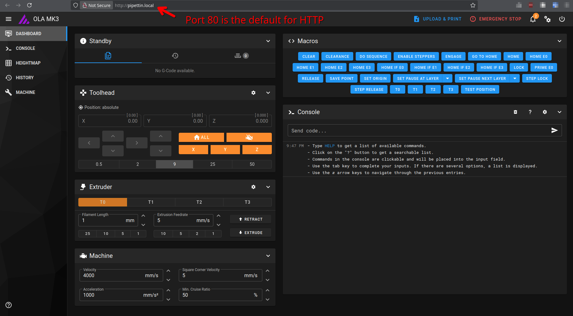
To access Mainsail:
- Open a web browser.
- Enter the address of the Raspberry Pi, as shown in the image below.
- The address was obtained during the Software Setup guide (the user guide may also help with this).
- Mainsail should open at the main control screen.
- Optional: it may be convenient to open a second browser tab, and open Mainsail's "Machine" page. This makes it easier to test configuration changes and monitor the state of the endstops while operating the robot from the main screen.
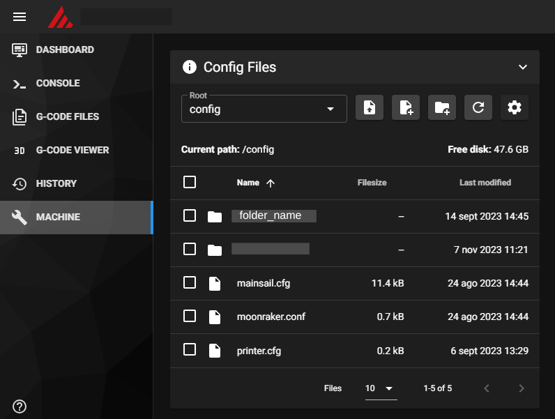
Mainsail screens
Main control screen (right) and Machine page (left):
Alternatives to Mainsail
Mainsail is not the only interface for Klipper, but its the one we've used for the Pipettin Bot.
You may also edit configuration files as you would edit text files on a remote machine: through SSH and a text editor, or using JupyterLab.
Firmware
This section holds instructions to compile and install Klipper on a controller board (a.k.a MCU).
Official Klipper docs
This guide should contain enough information to the firmware for the Pipettin' robot going.
More details available at Klipper's documentation.
Before you start, stop the Klipper service:
# If using systemd:
sudo systemctl stop klipper.service

# If using the user unit:
# systemctl --user stop klipper.service

# Older systems use "service".
# sudo service klipper stop
Select a board
On the Raspberry Pi, run the following commands:
- In the menu that appears, select the microprocessor that corresponds to your Arduino.
- For the Duet2 WiFi, select the
SAM3/SAM4/SAM E70 (Due and Duet)architecture, and theSAM4e8e (Duet Wifi/Eth)processor model, and you're done. - For Arduino UNO boards, select the
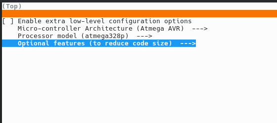
Atmega AVRarchitecture, and theatmega328pprocessor model. - Additionally, enable the
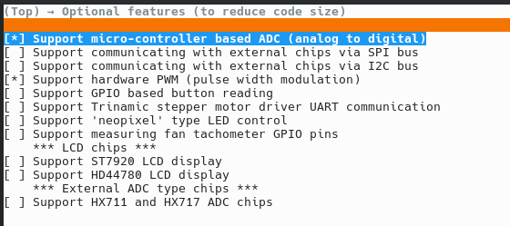
Enable extra low-level configuration options, and enter theOptional features (to reduce code size)menu. - There, uncheck all options. Then press ESC to return to the main menu.
- If you find errors, read the troubleshooting section.
- For Arduino MEGA boards, select the
Atmega AVRarchitecture, and theatmega2560processor model.
- For the Duet2 WiFi, select the
- Press
qand thenyto exit the application and save the configuration.- This will create a
.configfile.
- This will create a
Compile the firmware
Run the following command to compile the firmware:
Troubleshooting: error compiling for the Arduino UNO
Have you encountered an error while flashing for the Arduino UNO similar to the following?
/usr/lib/gcc/avr/5.4.0/../../../avr/bin/ld: address 0x800931 of out/klipper.elf section `.bss' is not within region `data'
If so, head to the troubleshooting section below.
Identify the boards
Before flashing the firmware, we need to identify which "serial devices" correspond to the boards connected to the Raspberry Pi (or Linux PC).
First connect the Raspberry Pi to the controller board with a suitable USB cable:
- Arduino UNO / Arduino MEGA: USB-A to USB-B cable.
- Duet2: USB-A to Micro-USB cable.
The following commands will list the serial device IDs of all connected USB devices:
# List MCUs by ID.
ls -l /dev/serial/by-id/

# You can also try listing MCUs by path.
# ls -l /dev/serial/by-path/
Now identify the device ID for your MCU. Here are some examples of what yours may look like:
- Original Arduino UNO:
usb-Arduino__www.arduino.cc__0043_557303238313513132A0-if00. - UNO "clone":
usb-1a86_USB_Serial-if00-port0. - Duet 2 WiFi:
usb-Klipper_sam4e8e_00323053354B50483031303332303133-if00
Identification of a board among many
An easy way to be sure about which ID corresponds to each connected device is to compare the output of the ls -l /dev/serial/by-id/ command before and after plugging it through USB.
There should be a new device listed in after connecting a board which is not found before. That one should be the device you just plugged in.
Troubleshooting: device not listed
If no devices are listed, try resetting the boards or changing the USB cable.
We have found that some boards do not like low-quality USB cables, and can fail to be recognized by the OS.
Running sudo dmesg -w and reconnecting the board may reveal connection issues.
Troubleshooting: duplicate IDs
Arduino clones may have identical IDs, which will conflict with each other if more than one is connected simultaneously. In this case, list them by path by using the second command above, and replace /dev/serial/by-id/ with /dev/serial/by-path/ in the commands above.
Install the firmware
- Run the following command, replacing YOUR-BOARD-ID with the serial device ID of your board, once for each MCU:
Troubleshooting: error flashing to the Duet2
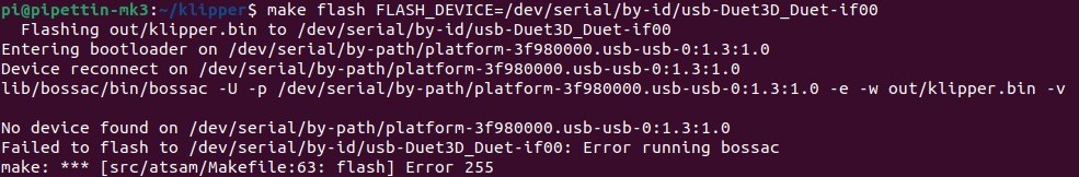
Have you encountered this error while flashing Klipper on a Duet 2?
No device found on /dev/serial/by-id/usb-Duet3D_Duet-if00
Failed to flash to /dev/serial/by-id/usb-Duet3D_Duet-if00: Error running bossac
make: * [src/atsam/Makefile:63: flash] Error 255
If so, read the troubleshooting section here.
- Restart the Klipper service:
# If using systemd:
sudo systemctl start klipper.service

# If using the user unit:
# systemctl --user start klipper.service
- Finally, use the identify commands to obtain the new serial device ID for your board, which might have changed after flashing.
You will need this value later on, when configuring the firmware, so write it down.
Using a different board
The procedure to use a different controller board is almost identical, as long as Klipper supports its microcontroller.
You would need to:
- Select the appropriate MCU with the
make menuconfigapplication. - Update all pins in the Klipper configuration files to match your board's connections.
- If the MCU on your board is supported by klipper, you will find most of the pin assignments pre-configured in the Klipper example configurations forlder. Use these as a base.
- To fine-tune and check pin assignments, read the connections section.
Running an OT2 with Klipper
You can definitely install Klipper on existing robots, such as the smoothieboard on an OT2, and use it with Pipettin's software.
Sounds fun! Let us know if you want help with this.
Connections
Connecting boards to motors and limit switches (a.k.a. endstops) is a critical step. Failing to connect them properly will damage your electronics.
Here are a few pieces of advice, before you start:
- Completely remove power from the controller boards before connecting or disconnecting any motor. Else, you may destroy your stepper motor drivers.
- Each board is different. Triple-check the polarity and wiring of your cables, such that they match the pinout on the controller board. Else, you may damage or destroy your controller board.
Overall, we wire the motors and endstops by following the lables on the controller boards, when available. Refer to the documentation of you board's manufacturer, linked in the pin names section.
Example cases
For example, connect the X-axis stepper to the 4-pin connector labeled "X-axis", and it's endstop to the connector the corresponding label.
On a Duet2 board, the remote actuator must be connected to the connectors labeled E0, and the first tool to the E1 connectors.
On a CNC-shield board, the remote actuator must be connected to the connector labeled A, and the first tool to any axis of the second CNC-shield (setup as a secondary MCU).
Pin names
Klipper uses microcontroller pin names, which is a generic way to address pins regardless on which board they are mounted.
This means less work for firmware developers (and more work for us users).
Pin aliases
Aliases for pin names can be included in a Klipper config file. Aliases help reference pins by more readable names, that also relate to the lables on actual CNC boards (instead of unrecognizable microcontroller pin names).
Here we provide a short list of resources to help match these MCU pin names to the labels found on the CNC boards:
- For the Duet2 WiFi.
- Inspect Klipper's example configuration files: Duet2 or Duet2 + Duex (expansion board).
- Duet's official wiring documentation.
- For the Arduino CNC shield:
- Have a look at our CNC shield pin-out diagram and the official documentation.
- Example configurations for XYZ steppers and an extruder axis.
- CNC shield pin aliases can be defined for clarity.
- For a RAMPS v1.4 board:
- The RAMPS board schematics and connection diagrams from the official documentation.
- Example configuration for RAMPS.
- Our RAMPS v1.4 pin aliases and the official Arduino MEGA pin aliases.
- The Arduino MEGA pinout, another MEGA pinout or the definitive pinout.
Pinout diagrams
The pin map below is for the Arduino CNC-Shield v3.0:

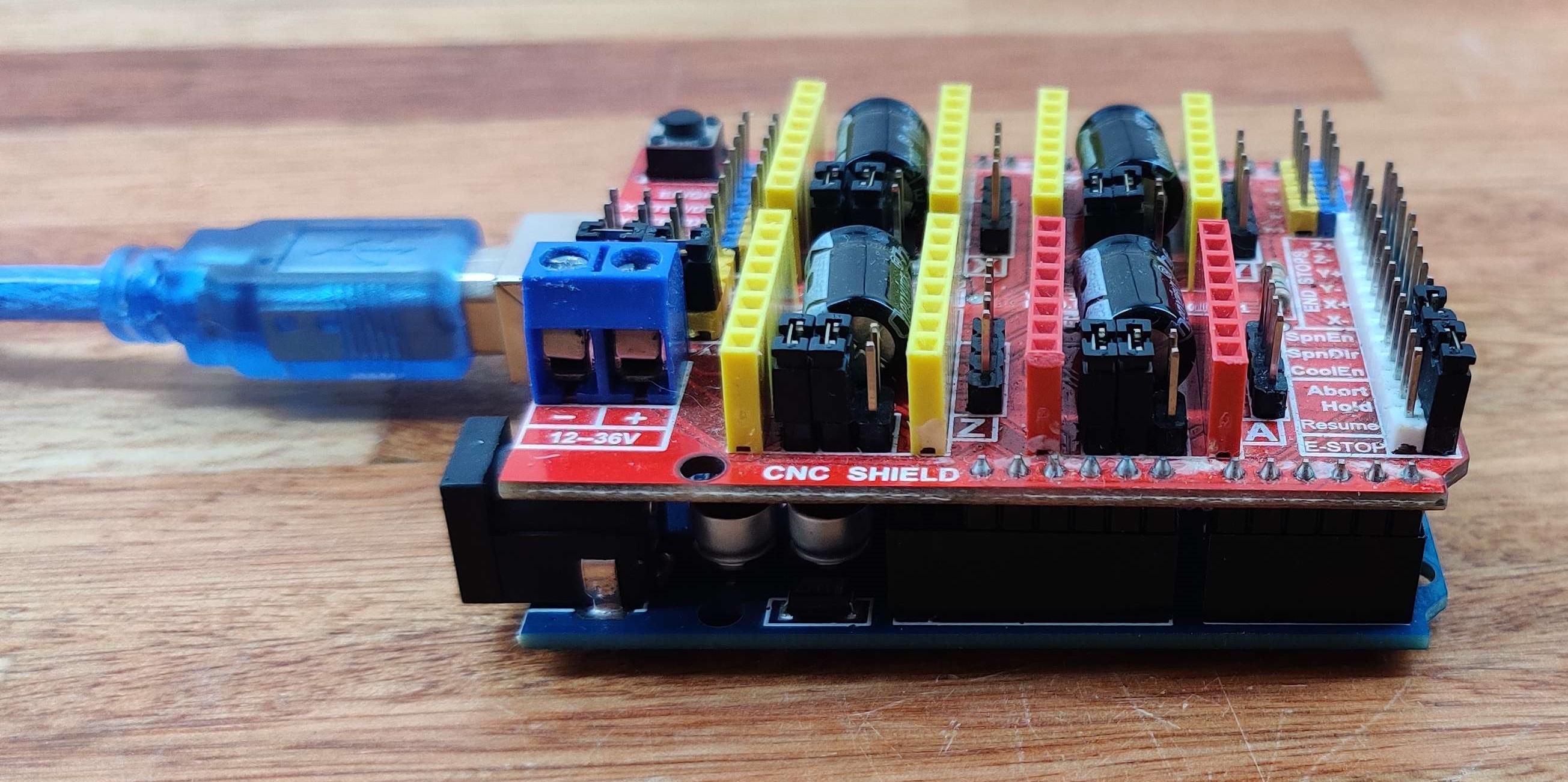
CNC shield
The Arduino CNC shield v3.0, originally developed at Protoneer.
Connections (main MCU):
- Add two jumpers to the microstepping configuration headers, located at each stepper driver slot of the CNC shield (as shown on the image below).
- This will set ⅛th microstepping on each driver. You can also try 1/16 microstepping, which will probably be smoother.
- Add jumpers to configure an independent "A" axis, as shown on the image below.
- Note that this maps
SpinDir(PB5) andSpinEn(PB4), toAdirandAstep, respectively. - This means that the
SpinDirandSpinEnboard pins are taken by the A axis, and can not be used for something else; instead use a free adjacent pin (e.g.Resume) if you need one.
- Note that this maps
- Install the stepper drivers on the board (mind the orientation).
- Connect the X, Y, and Z motors to their corresponding connectors on the board, as indicated by the lables written on them.
- Connect the remote actuator's motor to the "A" axis slot.
- Connect the X, Y, and Z endstops to their corresponding connectors on the board.
- In the CNC-shield, the "negative direction" endstop connectors (e.g "-Z") use the same pins as the positive (e.g. "+Z") can can't be used for other purposes. Leave them disconnected.
- Connect the endstops of the remote actuator using one of the available pins (
A0-A5, pin names explained above).- For example, we used the "Coolant Enable" pin, which corresponds to
PC3/A3.
- For example, we used the "Coolant Enable" pin, which corresponds to
Microstepping pin headers: found next to the larger capacitors, and will be hidden under the stepper drivers if they are already in place.
A-axis enable pins: add a pair of jumpers to the A-axis configuration header, in the lower position.

Connections (secondary MCU):
- All motors and endstops used by pipette tools will be connected to the secondary CNC-shield, which provides 4 additional slots.
- The steps above (for the main MCU) apply to this MCU as well.
- Connect E1 to the X slot, E2 to the Y slot, E3 to the Z slot, and E4 to the A slot.
Configuration notes:
- The "heater pins" of the remote's stepper should be to unused pins on the CNC shield. Do not use these for anything else.
- These pins need to be configured, but are not actually used by a non-heating extruder like syringes.
- For example, on a CNC shield we have used the SDA and SCL pins (
PC4/A4andPC5/A5, respectively).
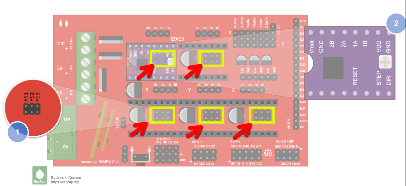
RAMPS board
The RAMPS v1.4 board, originally developed by the RepRap community.
Connections:
- Add two jumpers to the microstepping configuration headers, located at each stepper driver slot of the CNC shield (as shown on the image below).
- This will set ⅛th microstepping on each driver. You can also try 1/16 microstepping, which will probably be smoother.
- Install the stepper drivers on the board (mind the orientation).
- Connect the X, Y, and Z motors to their corresponding connectors on the board, as indicated by the lables written on them.
- Connect the remote actuator and pipette motors to the E-labeled slots.
- Use
E0for the remote actuator, andE1for the pipette.
- Use
- Connect the X, Y, and Z endstops to their corresponding connectors on the board.
- In the CNC-shield, the "negative direction" endstop connectors (e.g "-Z") use the same pins as the positive (e.g. "+Z") can can't be used for other purposes. Leave them disconnected.
- Connect the endstops to their corresponding connectors on the board.
- Connect the X, Y and Z endstops to the +X, +Y, and +Z headers on the RAMPS board.
- The endstops for E0 and E1 should be connected to the slots for the "-Z" and "-Y" endstops (i.e. the "negative direction" stops).
Microstepping pin headers: found next to the larger capacitors, and will be hidden under the stepper drivers if they are already in place.
Power supply:
- Warning: RAMPS is not compatible with 24V input voltages, unless modified.
- Switch to a 12V power supply, or modify the board as instructed in the official documentation.
Configuration notes:
- Use the matching base configurations provided by us, which are based on Klipper's example configs.
- The "heater pins" of the remote's stepper should be to unused pins on the CNC shield. Do not use these for anything else.
- These pins need to be configured, but are not actually used by a non-heating extruder like syringes.
- Klipper configuration example for RAMPS: https://github.com/Klipper3d/klipper/blob/master/config/generic-ramps.cfg
Duet2
The Duet2 WiFi board, developed originally by the Duet3D team.
Connections:
- Connect the motors to their corresponding connectors on the board, as indicated by the lables written on them.
- Use the matching base configurations provided by Klipper's example configs.
- Use
E0for the remote actuator, andE1for the pipette.
- Use
Configuration notes:
- On a Duet, the microstepping values on TMC drivers are set through software, and read from the configuration files.
- Heater and sensor pins for "extruder axes" need to be defined in the configuration, but will not be physically connected to anything (when using pipette tools).
Microstepping
Considerations:
- Using lower microstepping values will increase noise.
- Intermediate values are ideal (e.g. 16).
- Using higher microstepping values may introduce issues (e.g. lower torque or MCU overloading), and has diminishing returns. High values may not lead to increased precision, which also depends on the quality of the stepper motor, the mechanics of the actuator, and the applied load.
Instructions per board:
- On Duet2 boards, this is set through firmware configuration.
- On CNC shield and RAMPS boards, add jumpers to set microstepping to ⅛ or 1/16, according to your drivers, and update Klipper's configuration to match.
Firmware Configuration
For this section, you'll need:
- A Raspberry Pi set-up and running, and its current IP address.
- Control boards with Klipper firmware installed, and the unique path to its serial port.
- Electronic connections between the boards and motors, limit-switches, etc.
Before making changes to the configuration, study the following documentation:
- Klipper's Configuration Reference (common settings).
- Klipper-for-CNC Configuration Reference (fork-specific settings).
Here we provide a few configuration templates, to help you get started.
Base configuration
Each version of the robot has a defined set of Klipper configuration files. You can get them from the configs folder at the main repository.
These configurations differ mostly on the combination of MCUs that those versions use (e.g. Duet2 only, multiple CNC-Shields, RAMPS, or combinations of these).
Disclaimer
We provide these configurations as a base, but checking that they match your setup is up to you. Double check microstepping, rotation distance, and axis limits, and the polarity of direction and endstop pins.
The README.md files in those directories briefly describe what each configuration set is meant for.
Follow Klipper's configuration check guide to help confirm the pin settings. You may skip the temperature-related checks, unless you are actually using plastic extruders or heated beds.
Because you may have already downloaded the main repository to a directory named pipettin-bot at the home folder, those configurations should already be available to you locally at ~/pipettin-bot/code/klipper-setup/configs/.
First, copy the base configuration files to Klipper's printer_data/config:
# This will overwrite the default contents.
cp -r ~/pipettin-bot/code/klipper-setup/configs/* ~/printer_data/config/
By default, the base configuration uses printer_minimal.cfg, a barebones configuration. This lets us test that the host can connect to the firmware.
- Open
~/printer_data/config/printer_minimal.cfgfor editing. - Replace the serial path under the
[mcu]section with the one you obtained after flashing the firmware. - Restart klipper, and open Mainsail. Klipper should start without issues.
To select a useful base configuration, edit the top-level ~/printer_data/config/printer.cfg file, and select one that is closest to the robot you are building (e.g. 2x-CNC-Shield, Duet 2 Wifi, single-tool, multi-tool, etc.). You may use Mainsail's configuration editor or nano.
For example, use an include line in the top-level printer.cfg file looking like this:
Using comments to disable configs
If there are other lines including printer.cfg files from other subdirectories, you must comment them out by adding a # symbol, as shown below.
Only one printer.cfg file must be included here, unless two or more boards are connected and in use.
Finally, make changes to the base configuration you've selected, if needed, by editing the files inside the selected folder.
- Update the
[mcu]section of the active configuration, using the one you obtained after flashing the firmware. - Follow the steps below to fine tune the configuration to your setup.
Uploading configs through Mainsail
You can also open Mainsail in your browser and upload them on a folder on the MACHINE menu. We also recommend to have your own folder in order to create a copy of the following files. By doing that, you can modify them freely and keep a backup.
Origin
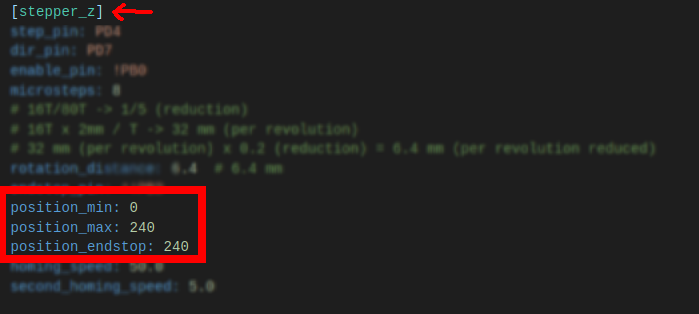
The maximum and minimum positions set in the [stepper] configuration section determine the motion limits.
The physical location of the macine's origin of coordinates is then set by te endstop_position setting in those sections.
Only the origin of the Z-axis is critical, which means that the following settings in [stepper_z] must be correct:
position_min: is set at 0.position_max: must be set such that the headplate touches the surface of the baseplate atZ=0.position_endstop: must be set equal toposition_max.
The procedure to correctly set this value is explained in the calibration guide.
Remote actuator
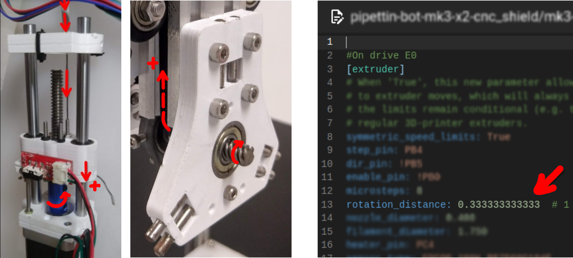
The stepper motor for the remote actuator must be defined as the [extruder] section, and must be selected when the the T0 GCODE command is sent.
The direction pin of the remote must be set such that:
- An "extrusion" moves is in the positive direction (i.e.
G1 E1), which corresponds to releasing the tool. - A "retraction" move is in the negative direction (i.e.
G1 E-1), which corresponds to locking the tool.
The base configurations specify that its endstop is in the maximum position of the axis, and the minimum is fixed at 0.
This maximum position limits the maximum travel of the remote, and will be calibrated later on to prevent two issues:
- Loosening the belt tension completely, such that it may "sag" out of the Z-axis profile, and jam with its V-wheels.
- Collisions with the top-end of the remote.
The rotation_distance parameter maps stepper rotations to linear advance of the headplate's leadscrew (not of the remote's carriage). You should not need to change this.
Tool-changer rotation distance math
By combining the ratios of each component we can calculate the toolchanger's distance per rotation parameter:
- Remote stepper (2mm lead): bv → 2 mm advance → 1 GT2 belt tooth
- Headplate pulley (24T): 1 tooth → 1/24 pulley revolutions
- Headplate leadscrew (8 mm lead): 1/24 revolutions → 8 mm * 1/24 →
1/3 mm
Advanced configuration
This section provides brief explanations of the main configuration files and the "sections" within.
For a more comprehensive understanding, we highly recommend referring to Klipper's Configuration Reference as it was our source of information for this setup.
Because we have forked Klipper for this project, a few configuration options (e.g. extruder_home) are only documented in the klipper-for-cnc repository at GitLab.
printer.cfg
This file is the central configuration file, it's commonly used to define fundamental settings for your robot.
Here you may, for example, specify your machine's kinematics (e.g. cartesian_abc), withing in the [printer] section of the file.
The remaining configuration options have been organized into different files, which must be "included" in order to have an effect.
Additional configuration files are included with the following syntax:
[mcu]
You must add the paths of the serial devices of each controller board in [mcu] sections.
If we used two Arduino boards, we would include both of them as shown below:
[mcu] # main mcu, used for the XYZ axes.
serial: /dev/serial/by-id/arduino_id_1  # <-- update this value with yours

[mcu tools] # second mcu, used for the tools.
serial: /dev/serial/by-id/arduino_id_2  # <-- update this value with yours
You can obtain the MCU IDs with the ls -l /dev/serial/by-id/ command, as previously explained.
[stepper]
This section defines settings for different stepper motors (X, Y, Y1, and Z) and end-stops that control the movement of different axes. Each [stepper_...] section contains specific parameters to the corresponding motor configuration.
The pin configuration in this file must reflect exactly the connections made in the electronics assembly guide (specifically the stepper motor and endstop connections sections).
Note
Aways triple-check pin assignments and connections before powering on the machine.
We've set aside files specifically to configure the stepper motors and end-stops for the micropipette tools, which are configured as "extruders". They contain essentially the same settings as the steppers_xyz.cfg files.
The key distinction lies in the specific pin referencing method required here, because the tools may be connected to a "secondary" MCU.
As mentioned in the mcu section, the second MCU is labeled as [mcu tools]. Since we've connected the tools' electronics to this second Arduino, the pin referencing should follow this syntax:
Note
Note the addition of "tools:" right before the pin's name (PD4). This indicates that the pin is on the tools MCU, and not on the main MCU.
[extruder]
The [extruder] sections define steppers that associate to the E axis in GCODE commands.
- The main extruder section is
[extruder], which we use for the remote actuator, and is activated with theT0command. - Additional extruder sections are defined for tools (e.g.
[extruder1]/ E1 /T1,[extruder2]/ E2 /T2, etc.).
These sections require pins for temperature control, that we will not be connecting to any sensor or heater, in the case of pipette tools. For this reason we need to disable tempearture checks in all [extruder] sections.
We also need to disable some features related to limiting plastic extrusion, speed, and others.
Here is an example of these overrides: stepper_remote.cfg
Note the following changes:
[extruder]
# ...
# ...
# Override temperature limits.
min_temp: -273.15
max_temp: 999999
min_extrude_temp: -273.15
# ...
# ...
# Override motion limits.
max_extrude_only_distance: 300
max_extrude_cross_section: 100
max_extrude_only_velocity: 2.0
# ...
Homing parameters are required:
Extruder homing commands
To home an extruder, an additional [extruder_home] section must be added, as explained below.
[extruder]
# ...
# Homing stuff
position_endstop: 9.8
position_min: 0.0
position_max: 9.8
homing_speed: 2.0
endstop_pin: ^!PC3
# ...
[gcode_macro]
The gcode_macro sections are used to define custom commands. For example, to set origins, homing axes, switching between tools, etc.
We define a few important macros related to:
- Tool homing (e.g.
HOME_E0commands, which require enabling extruder homing). - Tool selection (i.e. commands
T0,T1, ...). - Tool-changing macros common to all tools (e.g.
LOCK,ENGANGE, etc.) defined using DynamicMacros.
What is a Klipper macro?
In Klipper, a macro refers to a sequence of predefined commands grouped together under a single name. These macros simplify complex operations by allowing users to execute a series of commands with a single line of code.
Essentially, instead of manually inputting numerous individual commands every time a specific action is needed, a macro condenses these commands into a single command, making it easier to perform repetitive tasks or abstract complex actions.
Example macro
Here is an example macro that homes axes in a particular order:
Macro variables
We use macro variables like "active" with different values for each extruder section, in order to manage the state or status of each tool.
[extruder_home]
This section sets the homing configuration for homing extruder stepper motors. It defines commands for homing "extruders", which otherwise can't be homed.
The [extruder_home] sections define commands that are required by macros for tool-homing, which can be found after each of the tool's [extruder] definitions in the base configurations.
Full example
A full configuration for homing extruders is available at the main repo.
The following enables the HOME_EXTRUDER command for the main [extruder] section:
The following macro definition uses the new command to properly home the remote actuator:
[gcode_macro HOME_T0]
description: Homing macro for the main extruder (tool T0).
gcode:
  # Select tool T0.
  T0
  # Home the extruder.
  HOME_EXTRUDER EXTRUDER=extruder
mainsail.cfg
The mainsail.cfg file is a configuration file for Mainsail, a web font-end to Moonraker and Klipper.
This file defines various custom G-code macros and settings to control how your robot behaves during certain events such as pausing, resuming, canceling prints, or moving the extruder. If these macros are not included, several harmless warnings will appear. We recommend not making any modifications to this file.
We use a custom replacement because the original macros are printer-centric, and caused problems with the normal funcion of a non-printing machine.
Custom mainsail.cfg
Unfortunately Mainsail overrides basic commands and uses custom GCODE macros in ways that do not make sense for generic robots (e.g. CANCEL_PRINT, PAUSE, and RESUME overrides, and _CLIENT_EXTRUDE macros for manual extrusions).
We have modified this file to avoid problems with those overrides, saved as mainsail_dummy.cfg.
End-stops
An endstop (or limit switch) is a switch or trigger that is placed at a particular position of an axis, usually at its limits. In this way, the motion of the axis can trigger the switch, and this information can be used by the CNC machine to determine its position.
In other words, an endstop is a reference point that can turn relative motion to absolute motion:
- In version MK3 of the robot, these sense the maximum position of each axis on the motion system, including the tool-changer's remote actuator.
- On pipette tools, the endstop's position corresponds to the zero coordinate instead. This is such that an extrusion/dispense move occurs in the positive direction of the tool's coordinate system.
Endstops are configured by setting the value of the endstop_pin parameter, within each [stepper] and [extruder] section section. Adding an endstop to an extruder axis is a feature of our Klipper fork, not found upstream.
For details, read Klipper's configuration reference for steppers.
Endstop trigger polarity
We use the ubiquitous mechanical endstops, originally designed by Makerbot.
These require pin polarity inversion in the endstop_pin fields of stepper and extruder sections.
You will likely need to prefix all pin names with an exclamation mark "!" for them to trigger as intended (e.g. !PC14).
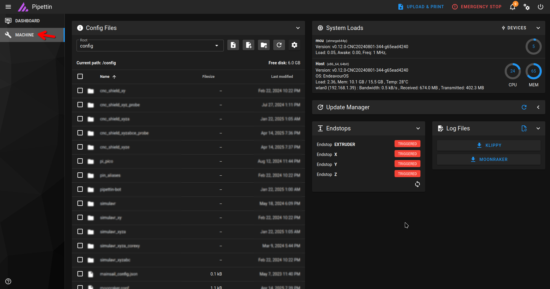
To inspect the trigger status and polarity of an endstop:
- Move a machine's axis by hand, clear of the endstop.
- Browse to Mainsail's "Machine" tab, and refresh the endstop status panel (image below).
- The corresponding endstop's status should be OPEN (i.e. not triggered).
- Gently move the axis by hand, until it hits the endstop, and refresh the panel again.
- The corresponding endstop's status should be CLOSED (i.e. triggered).
- Move the axis away from the endstop, and refresh the panel again, to check that it turns back to OPEN state (i.e. not triggered).
- If the endstop is not triggered (or open) when it should be, the polarity of the endstop pin is inverted.
- Fix this by adding or removing an "!" prefix to the endstop pin name in the
endstop_pinfield of the corresponding stepper or extruder section.
- Fix this by adding or removing an "!" prefix to the endstop pin name in the
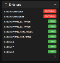
The status of each endstop can be monitored through Mainsail, in the "Machine" tab. As you make changes and test them, hit the refresh button.
Motion system endstops
Check and adjust the following for XYZ axes and the remote actuator (E0):
- The configuration of end-stops (e.g. active low/high, pull-up/pull-down resistors) using the
endstop_pinparameter at each[stepper_]section, and in the main[extruder]section. - The mount points of all end-stops, such that they trigger properly.
- The set-screw and nut on the Z-axis that triggers its end-stop.
Tool endstops
Check and adjust the following for the pipette tool axes (E1, E2, etc.):
- The configuration of end-stops (e.g. active low/high, pull-up/pull-down resistors) using the
endstop_pinin each additional[extruder1/2/...]section. - The position of the tool's main endstop. Not too high (to prevent leaks) and not too low (to prevent loss of range).
Additional configuration:
- Tip sensor endstops (if any, as found in the "Gilson" pipette adapter).
- Parking post sensors (if any, as found in the old
MK0prototype of the robot).
Current adjustment
Current limiting in stepper drivers comes at the cost of reduced torque, which may cause loss of steps in situations requiring it (e.g. when changing tools, placing tips, high acceleration,etc.), but also protects the motors (and their supporting structures) from overheating.
The main trade-off here is the following:
- Limiting the current is a good idea!
- Stepper drivers will run cooler and last longer.
- The motor coils will be damaged by the excess heat produced by excess current.
- Furthermore, the 3D-printed supports for the steppers may waken or deform under this heat.
- However, a lower current limit will cause loss of steps during high-force moves (i.e. docking tools and placing/ejecting tips).
Different boards limit the current in different ways:
- Basic stepper drivers found in CNC shields and RAMPS (e.g. A4988 or DRV8825) limit the maximum current through the "reference voltage" (Vref). The reference voltage (Vref) in a stepper driver is what limits current flow through your steppers, and is adjusted using a multimeter.
- TMC drivers found in Duet2 boards limit the current through the
run_currentparameter, and theidle_current_percentparameter (which reduces the current when the stepper is idle) set through Klipper's configuration.
How hot is too hot
How hot is too hot for a stepper motor?
If you can keep your fingers on it, then it's not bad for the stepper. This is around 60ºC which is not terrible for a motor, but it will tend to soften 3D-printed parts.
Any plastic parts will become softer and probably warp over time if exposed to minor heat, and deform immediately if the stepper is too hot.
In some versions of the robot, the steppers are secured to the structure using 3D-printed parts. Excess temperature will deform or even melt the plastic parts, so limiting the current may be a great idea in the mid-term.
Perform the same check on the stepper driver ICs, present on the CNC board. These must also be kept cool. If they are not, consider adding heatsinks over the ICs and fans to the board.
Consider lowering the current limit on the stepper motor drivers by:
- Changing the Vref on the CNC shield drivers (e.g. A4988 or DRV8825).
- Changing the current limit on TMC drivers through Klipper/Mainsail.
Learn more over here: https://3dprinting.stackexchange.com/a/8485
Check connections
A few checks before powering anything on:
- Logic: triple-check all connections to endstops and sensors (voltages, polarity, etc.). Any accidental shorts will cause damage to your electronics.
- Power: triple-check all power connections (voltages, polarity, etc.), ensuring that nothing will catch fire or explode.
Disclaimer
Failing to connect things properly will damage your boards, set something on fire, or possibly harm you. These guides are provided as is, with no guarantees, and you are responsible for their use.
Pololu drivers
The current limit in the A4988 and DRV8825 divers can be changed by setting their "reference voltage" (i.e. Vref) to an appropriate value.
The procedure involves:
- Choosing a current limit:
Imax(from your motor ratings) - Figuring out the value of the sense resistor:
rs(guides linked below) - Calculating the target voltage value:
Vref(equation below) - Measuring the present
Vrefvoltage. - Turning the adjustment screw on the driver.
- Repeat steps 4 and 5 until the measured
Vrefmatches the calculated targetVref.
You'll need:
- The resistance value of the "sense resistor" on the driver (a.k.a. rsense or Rs).
- A multimeter with fine probes (not crocs).
- A small phillips screwdriver (preferably plastic).
- The current limit of your steppers.
- Patience.
Rs values may vary
Even though A4988 drivers are sold under the same name, there are several variants each with different rs values.
Good reads on Vref adjustment
The all3DP and E3D guides are very helpful:
- RepRap's guide has a section about finding the value of the sense resistors.
- E3D's guide archive for the A4988 driver is great.
- E3D's guide archive for the DRV8825 driver is great.
- All3DP's Vref calculator is also good.
- Ardufocus' guide
- Guía de Javier (en español).
The formula for the reference voltage is the following:
Vref = Imax x (8 x rs)
Warning
When using the multimeter, be very careful not to touch or short any other pins or components on the controller.
Follow these steps to adjust the reference voltage:
- Find the maximum current rating of your stepper motors in their specifications or datasheets. Choose a lower target current (e.g. 25% of maximum).
- Calculate the reference voltage (
Vref) for your particular stepper drivers and motors (e.g. A4988, DRV8225, and others). - Locate the
Vrefadjustment potentiometer on the drivers. - Connect the controller board to the power supply and turn it on.
- Probe the driver's
GNDpin with the negative end of a multimeter. - Probe potentiometer with the positive end of a multimeter.
- Note the voltage value measured by the multimeter. This is the present value of the reference voltage (
Vref). - Turn the potentiometer using a small screwdriver to change the reference voltage, and make a new measurement.
- You can also connect the positive end of the multimeter to the screwdriver's shaft with a crocodile clip, and make the adjustment while reading out the voltage on the multimeter simultaneously.
- Repeat steps 5-8 until the
Vrefreadout matches the target value calculated previously. - In the future remember to check the temperature of the motors. Lower the
Vrefif its too high.
Tip
If the voltage reading is 0, you may need to connect the microcontroller (in this case an Arduino) to a USB power supply as well.
Tip
If steps are lost at the maximum Vref/current setting, use larger stepper motors. Also consider using a PSU with a voltage that is close to the driver's maximum voltage rating. This helps them produce sharper steps.

TMC drivers
Current limits on the TMC drivers can be set by firmware configuration.
Klipper can set the current limit on TMC drivers. Lots of information can be found here.
TMC2660 drivers are found, for example, in the Duet2 WiFi board that we use in one variant of the Pipettin Bot. To set the current limit, edit the Klipper configuration files accordingly.
For example:
Tip
Additonally, it is important to set a "hold current" (or "idle_current_percent") that is high enough. Low hold currents may cause step skipping.
The A4988 and DRV8825 drivers do not have this feature, and will constantly draw full power when enabled. Read more about this here.
Tests
Electronics tests
TO DO
A guide is due.
- Motors.
- Direction.
- Connections.
- End-stops.
- Klipper: use mainsail to check that endstops are triggered when they should (e.g. check their state and trigger them manually).
- Update CNC configuration if necessary.
Motion tests
Warning
A guide is due.
- Set the origin by software (avoid homing moves at this stage).
- Send some commands for small displacements (e.g.
G1 X1), check that they turn in the expected directions. - Double check the end-stops, parking sensors, or probe sensors.
- Home the axes one at a time (e.g.
G28 X). Hold you finger above the emergency stop button, just in case. - Test torque with a tool-change.
Next steps
Congrats! You've setup the firmware for your robot. That was tough!
You may now:
- Continue to the object calibration guide: Calibration Guide
- Return to the assembly guide: Assembly Guide
Troubleshooting
Error while flashing: "address is not within region"
This error may be encountered while flashing for the Arduino UNO similar to the following:
/usr/lib/gcc/avr/5.4.0/../../../avr/bin/ld: address 0x800931 of out/klipper.elf section `.bss' is not within region `data'
This is because Klipper has not kept up with newer OS libraries, which have made the firmware too large for the Arduino UNO.
One fix is to disable all optional features in the make menuconfig tool. This will make the firmware smaller.
Then retry building and flashing the firmware to the UNO.
Note
Even when all optional features in make menuconfig are disabled, some may need to be disabled manually in the .config file. For example, I had to disable CONFIG_HAVE_GPIO_SPI and CONFIG_HAVE_GPIO_I2C.
Note that disabling CONFIG_HAVE_GPIO_ADC, which is ok since the UNO does not have GPIO ADC pins, causes a "protocol error" later on with the message Firmware constant 'ADC_MAX' not found.
To manually disable the optional features, edit the .config file.
Note
The .config file is created by the make config config, and does not exist before running it.
Manually edit the .config file in the klipper directory, such that it reads the following:
CONFIG_WANT_GPIO_BITBANGING=n
CONFIG_WANT_DISPLAYS=n
CONFIG_WANT_SENSORS=n
CONFIG_WANT_LIS2DW=n
CONFIG_WANT_SOFTWARE_I2C=n
CONFIG_WANT_SOFTWARE_SPI=n

CONFIG_HAVE_GPIO=y
CONFIG_HAVE_GPIO_ADC=n
CONFIG_HAVE_GPIO_SPI=y
CONFIG_HAVE_GPIO_I2C=y
CONFIG_HAVE_GPIO_HARD_PWM=y
CONFIG_HAVE_STRICT_TIMING=y
CONFIG_HAVE_LIMITED_CODE_SIZE=y
CONFIG_INLINE_STEPPER_HACK=y
Finally, run make clean and try running make once more.
Lost communication with MCU
This might be due to:
- Poor power supply on the Raspberry Pi.
- Bad USB cables.
- Interference issues (EMI) due to nearby electronics or motor/Pi power supply.
- Obscure USB connection issues that do now show up on
dmesg. - Check the
bytes_retransmitcount in the klipper logfile. If its high, there is a connection quality issue.
There are some guides on this already:
- Official docs: https://www.klipper3d.org/FAQ.html#i-keep-getting-random-lost-communication-with-mcu-errors
- Related post: https://klipper.discourse.group/t/lost-communication-with-mcu-mcu/3083/
Actions yo may take:
- Check the links above,
- Try reducing the baudrate (first in
make menuconfig, then re-flash, and set it in theprinter.cfgfile too). - To check if its the Pi's fault, or something else, try connecting the MCU to a PC with Klipper setup (guide here).
- If you're unable to resolve this, try another Pi, or use a PC.
Error while flashing: "Error running bossac"
This error may show up when running make flash on a Duet board, with more recent Raspbian distributions.
To flash Klipper to a Duet 2 Wifi board yo may need to:
- Compile Klipper for the Duet 2 WiFi, setting it to USB mode.
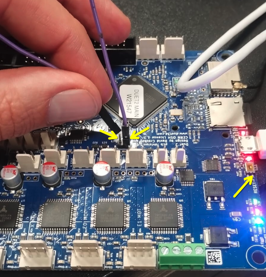
- Add a jumper between the "ERASE" pins on the Duet (image below).
- Press the RESET button (or try reconnecting power).
- Remove the jumper.
- Flash Klipper using make flash.
- Disconnect the board from power to hard-reset it.
- Run
ls -l /dev/serial/by-id/once more, the Duet should appear with a new name, similar tousb-Klipper_sam4e8e_003233535235534D3035303533303231-if00.- If the
lscommand still shows a name such asusb-Duet3D_Duet-if00, make sure that the device has been fully reset and reconnected through USB.
- If the
We have some additional notes on flashing klipper on the Duet in GitLab, and a workaround for this issue exists.
Duet2 disconnects after a firmware restart
Symptoms:
- The Duet2 fails to connect, and is not listed under
/dev/serial/by-id/ - A firmware restart causes the Duet2 to not reconnect correctly, and Klipper fails to find it on the usual serial port.
- In that state the
ls -l /dev/serial/by-id/command shows a Duet2 board with an incomplete name (e.g.usb-Klipper_sam4e8e_00313753595252533136303532303436-if00instead ofusb-Klipper_sam4e8e_00313753595252533136303532303436-if00) - The
sudo dmesg -wcommand shows warnings about not being able to reset the Duet, or saysunable to enumerate USB device. - The issue can be worked around by disconnecting the board from usb, and reconnecting it to a different USB port.
Solution:
- Re-flash the firmware from another operating system.
Related Klipper issue:
Arduino UNO connection times out
An error message appears in klipper's log:
An error message involving EMI (electromagnetic interference) appears in the Linux dmesg:
...
    ch341 3-1:1.0: ch341-uart converter detected
    usb 3-1: ch341-uart converter now attached to ttyUSB1
...
    usb usb3-port1: disabled by hub (EMI?), re-enabling...
    usb 3-1: USB disconnect, device number 7
    ch341-uart ttyUSB1: ch341-uart converter now disconnected from ttyUSB1
    ch341 3-1:1.0: device disconnected
...
This indcates electrical interference issues, affecting the communication between the UNO and the Pi.
Solution 1:
- Change the USB cable. Some cables are really bad at keeping EMI out, even if they are short and seem to be shielded.
Solution 2:
- Reduce baudrate to
115200:- Reduce baudrate to
115200in the klippermenuconfigtool, and re-flash the board. - Change the
baudparameter in the klipper configuration, and reboot.
- Reduce baudrate to
Navigation:
Previous: ← Assembly Guide | Next: Calibration Guide →