Knowledgebase
Everything "meta" about this project.
Where we work
- GitLab group:
- Repositories for hardware and software sources.
- Task tracking in an "agile" board of issues.
- How we use git.
- Discord server:
- Categories by project,
- Forums and working groups by area,
- Threads for mid-term objectives,
- Messages for daily multi-media logging.
- Home page: gardened documentation, made from daily logs.
- Objective documentation entries.
- Google Drive:
- Temporary folders for storage, sharing, and collaboration.
How we document
The most important documents are the documentation "templates", which are crucial to organize:
- The daily generation of source material for the documentation.
- And the writing of the actual final documentation.
A detailed explanation of how we develop towards documentation is available over here.
Note
Over the years I have learnt to greet friendly open source developers with a warm "where are the docs?" salute. Eveyone loves it.
Part labeling
Our part numbering schema available here
A detailed explanation of our part labeling method is available here
- Parts:
[Versioned Part ID] = [Part ID (part number)] + [revision number] - Assemblies:
[Versioned Assembly ID] = [Assembly ID (Assembly number)] + [revision number]
When can part names change?
- The revision number is only modified when a "slight" modification is made to a part or assembly; this mean that the modification does not make it incompatible with the parts or assemblies it originally interacted with.
- Part/Assembly IDs are incremented only when the modification on the part or assembly introduces an incompatibility with the parts or assemblies it originally interacted with.
Inspired by Jubilee's schema available here
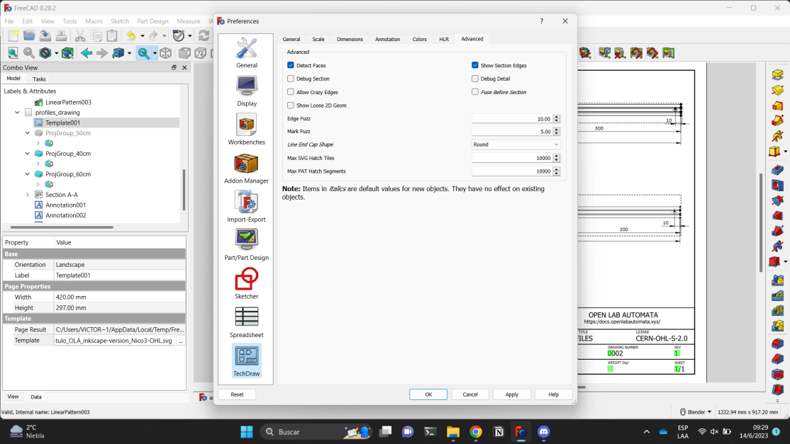
Technical drawings
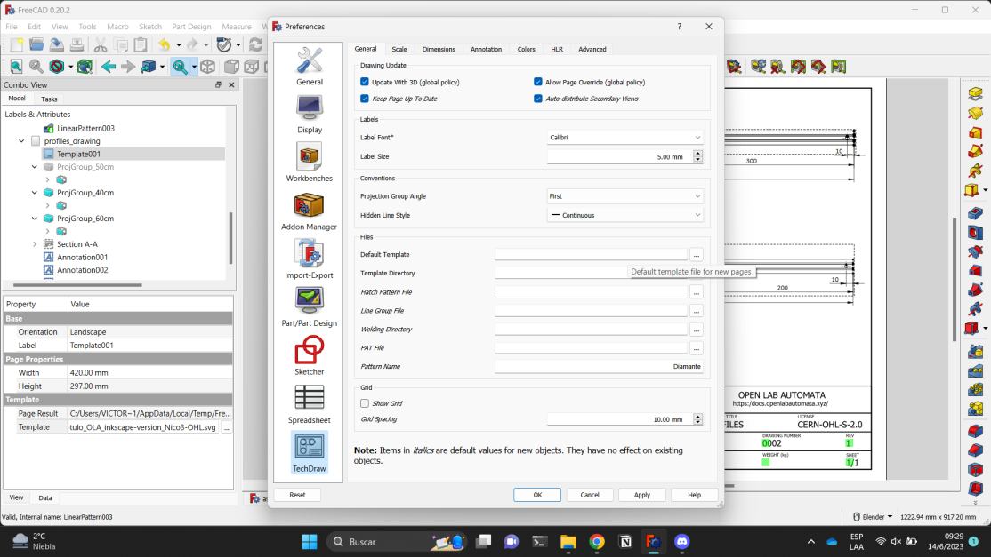
We make drawings with FreeCAD's TechDraw workbench: https://wiki.freecad.org/TechDraw_Workbench
We use a common TechDraw template for the project's drawings: TechDraw Template
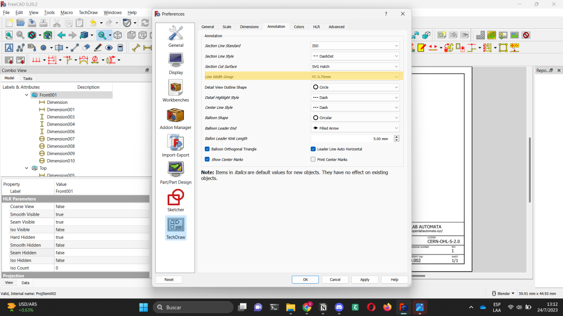
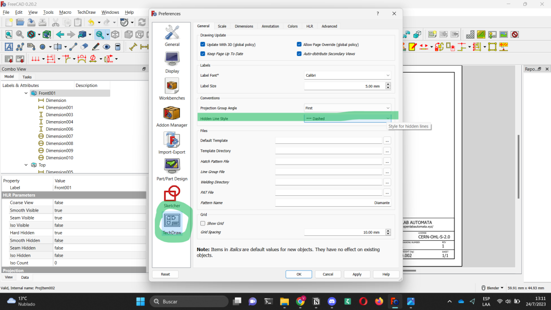
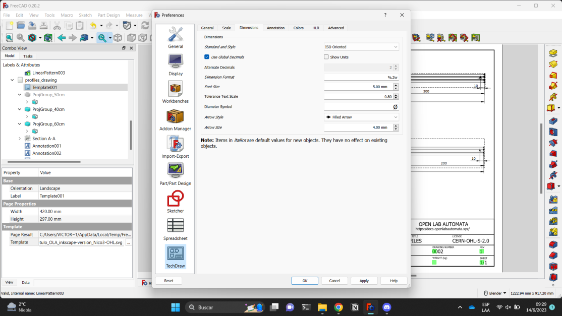
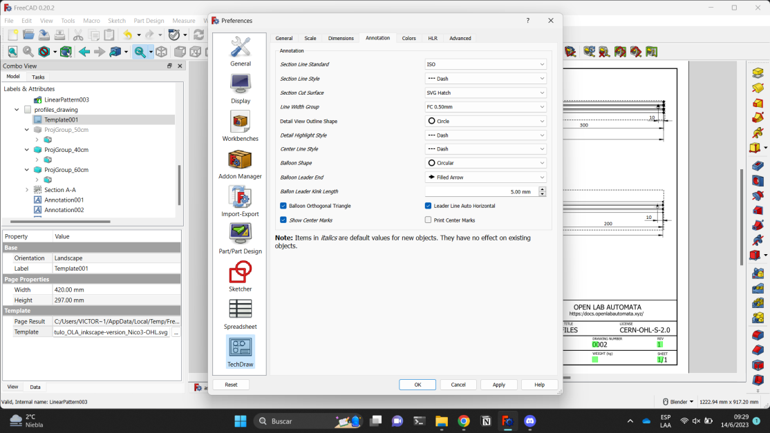
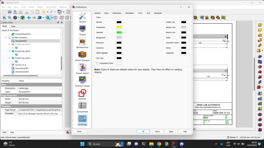
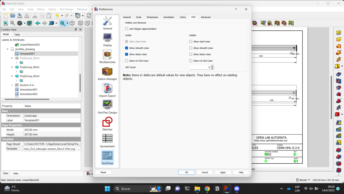
There are several parameters in TechDraw which can be adjusted:
- Line thickness
0.7(Line width group). - Show hidden edges as dotted lines (Hidden line style).
- To activate the visualization you have to access manually (blue: Hard hidden).
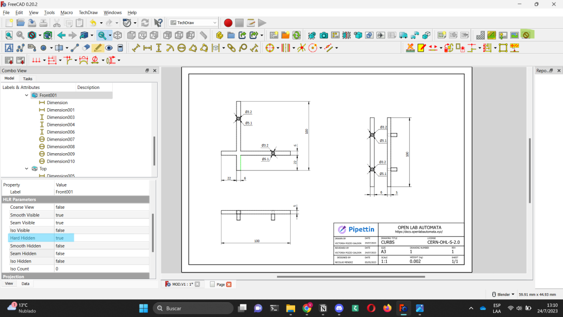
- Some useful tools:
- Hide edges (yellow: Hide edges): With this tool we can remove edges that have remained on the bodies, resulting from revolutions, etc.
- Print view (green: Print view): with this tool we can 'hide' all the annoying extra objects to have a clearer vision, without the need to export as pdf, as shown in the third image.
More screenshots:
Procedures
Manufacturing and design procedures.
Using the resin 3D-printer
To learn how to 3D-print, its parameters, the cleaning and hygiene environment needed for printing and the post-printing process, visit here.
Modelling in FreeCAD, preparing technical drawings for manufacturing
To learn how to model in FreeCAD, prepare technical drawings, edit FCStd. files, and more visit here.
Writing new code
Due soon: add links and explanations.
Cutting aluminum profiles
Band Saw
Instructions on how to use a band saw to cut aluminum profiles available here.
Miter Saw
Instructions on how to use a miter saw to cut aluminum profiles available here.
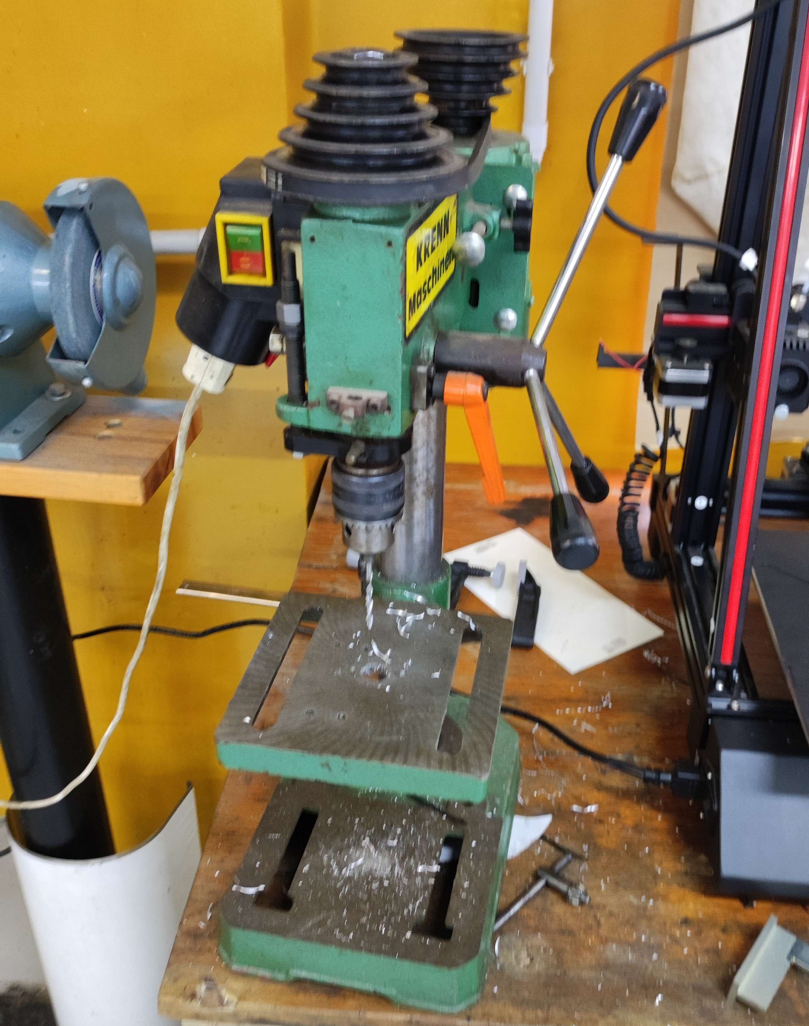
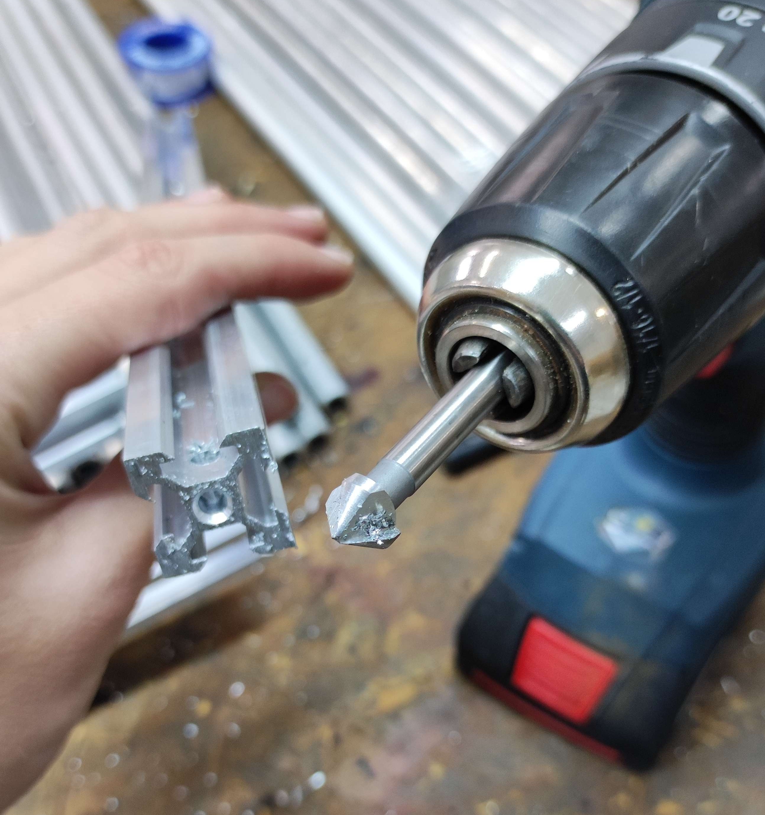
Drilling and Tapping
Drill press
A simple drill press:
Countersinks
Reference: https://en.wikipedia.org/wiki/Countersink
CAD software
FreeCAD
- Main: https://www.freecad.org/
- Wiki: https://wiki.freecad.org/
Workbenches:
- Gears
- Fasteners