Electronic Micropipettes
Electronic Micropipette
Overview
Our custom single-channel micropipette can dispense a wide range of volumes:
- 1000-100 microliters, using p1000 tips.
- 200-20 microliters, using p200 tips.
- and 20-2 microliters, using p20 tips.
Thanks to its tip holder, there is no need to swap between different tools when switching between different tips for different volume ranges.
The micropipette rests on a "parking post" mounted on the backpanel. The robot's tool-changer can pick it up, move it around, and park it, just as a PhD student would (?).
This section provides instructions for building the Pipettin bot's micropipette, including drawings, manufacturing instructions, design notes and other options you may want to consider.
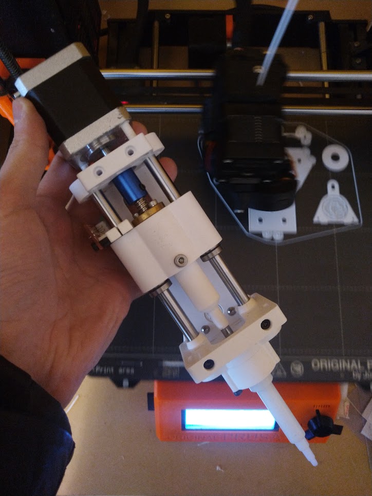
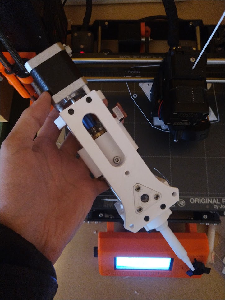
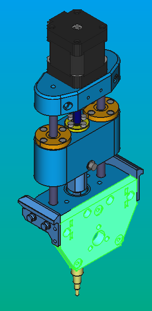
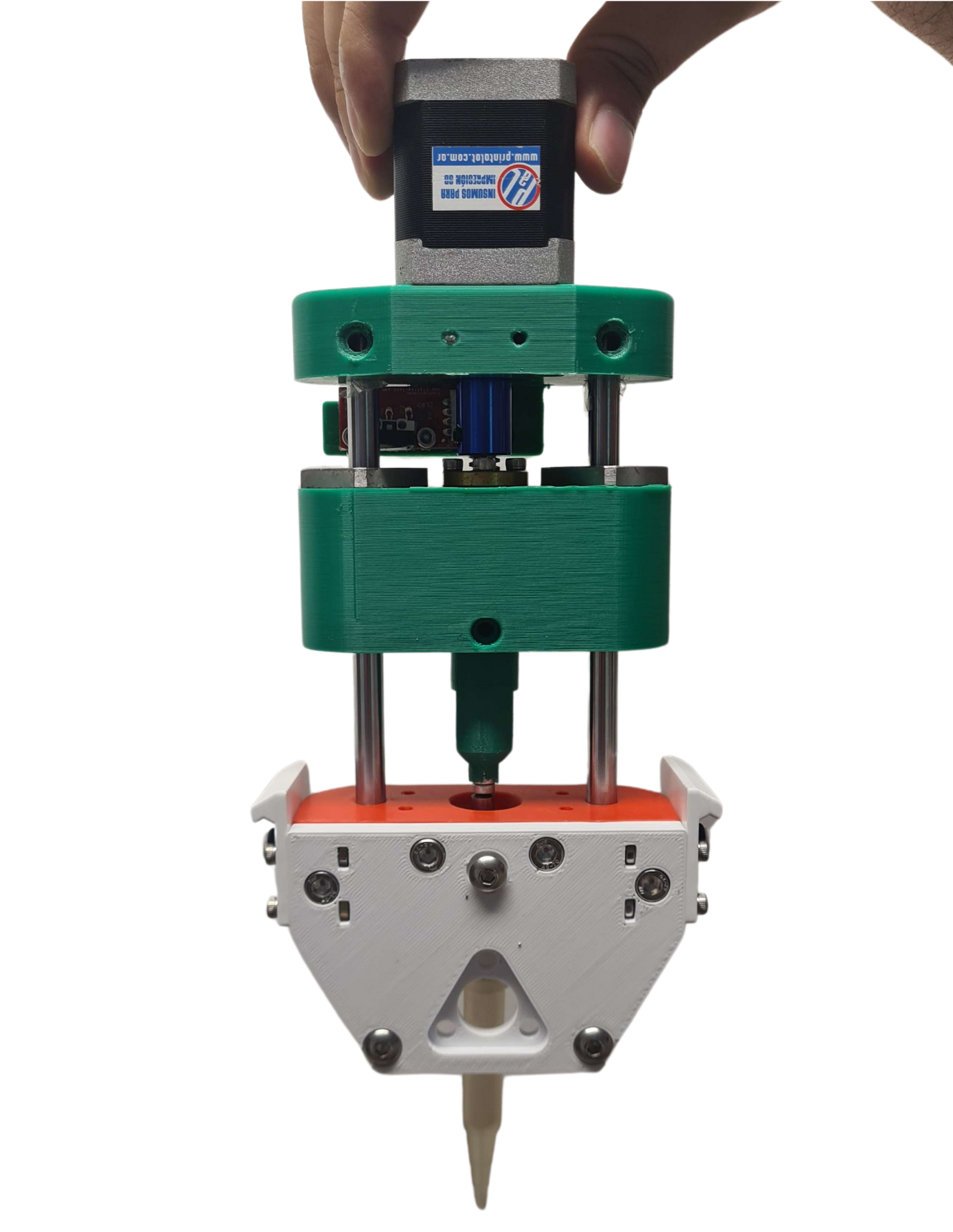
Micropipette and its tool-plate.
Usage
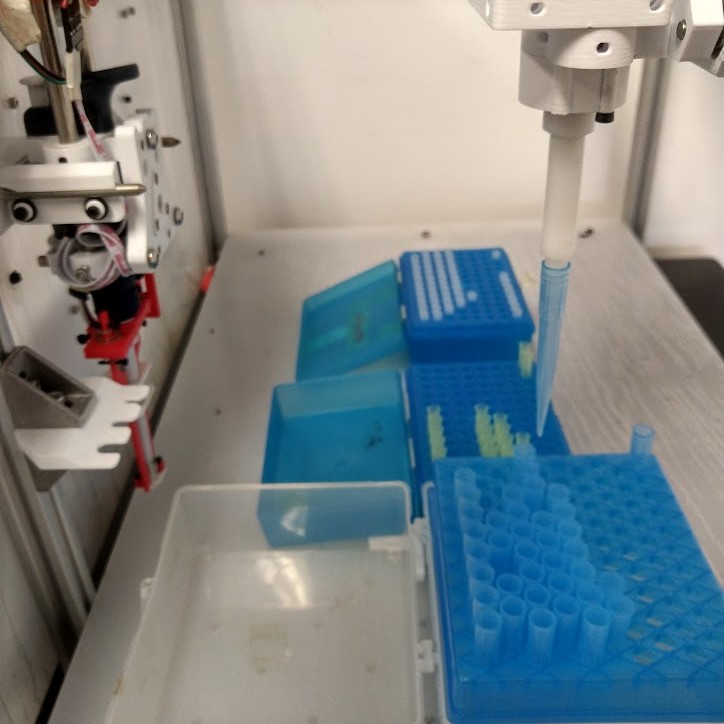
This micropipette was designed to be used by a robot and cannot be used manually with ease or precision. It is only intended for automated liquid-handling.
The tip-ejector mechanism is not a part of the micropipette itself. Instead, the tips are ejected by crashing elegantly agains a "fork" structure, mounted on a 20x20 aluminum V profile.
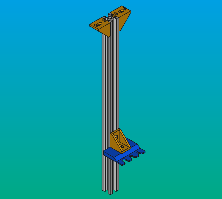
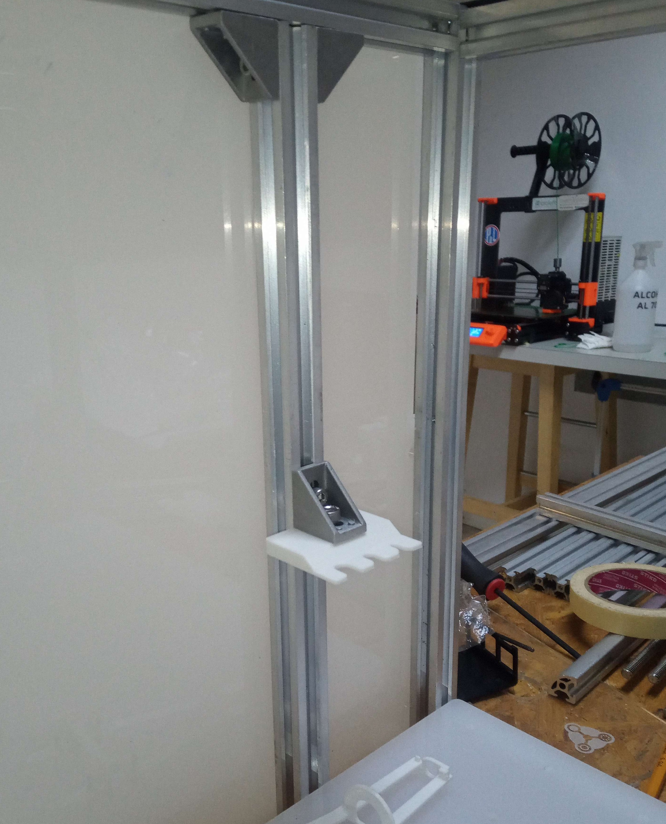
Tip ejector
The tool parking post is a fixture that is attached to the 20x20 aluminum V profile, where the tools are parked. The tool changer can then grab the tools, move them accordingly, and park them again. The tool parking post is a convenient way to park the micropipette or any other tool when they are not in use.
Each tool has its own parking post.
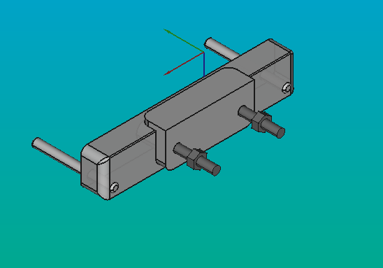
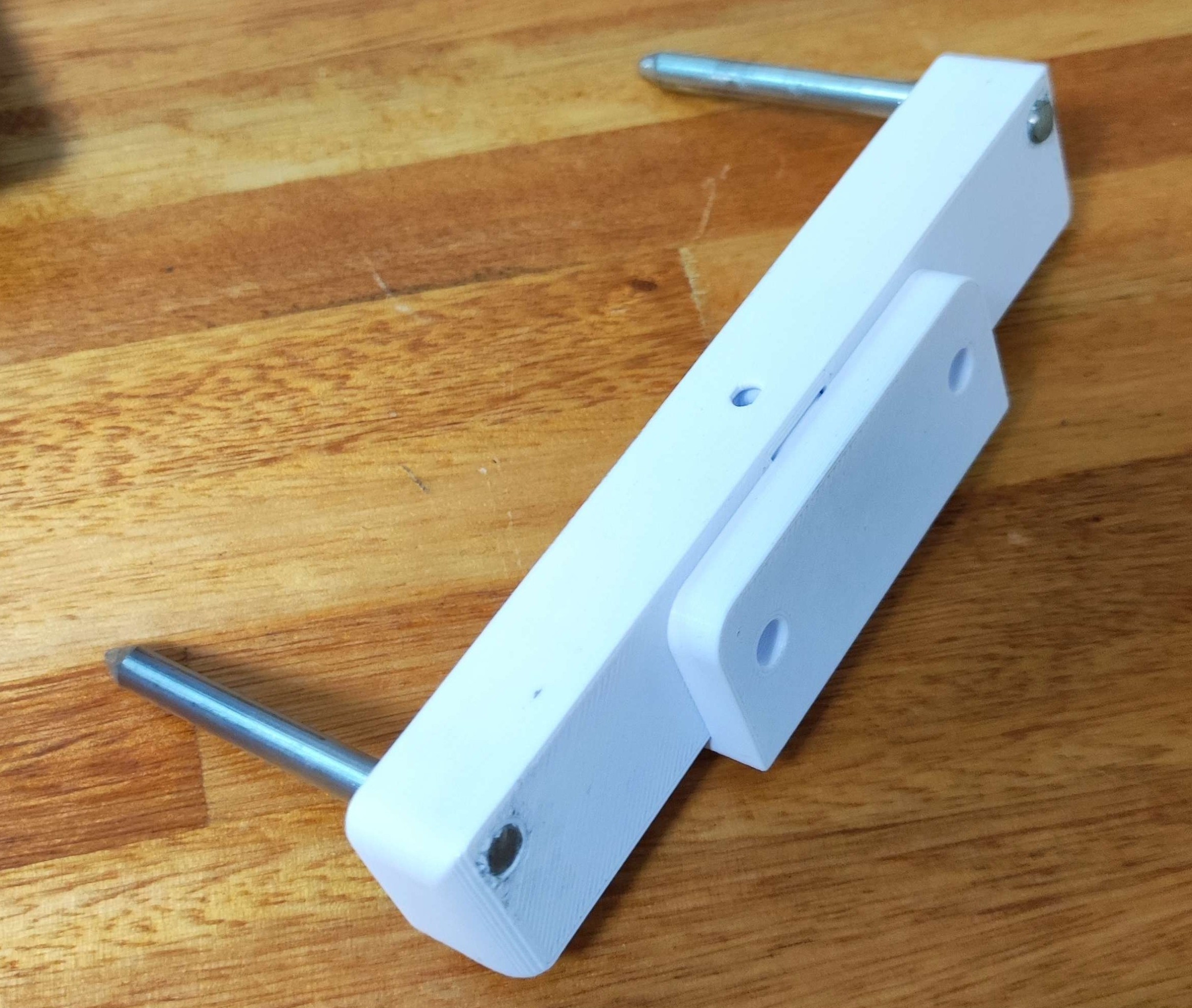
Tool parking post
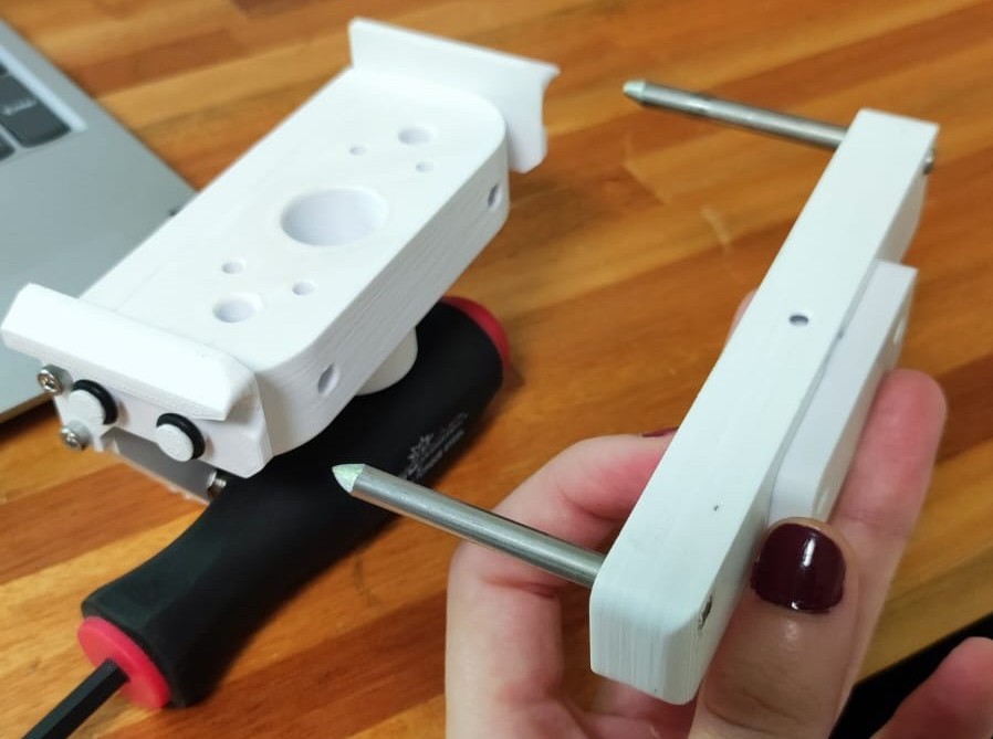
Tool parking and tool-plate
The tip holder mechanism can be 3D-printed in resin by SLA, or turned in a CNC lathe (with a few operations and tools). The 3D-prints are fragile, so we recommend the machined version.
Tip
The acetal (Delrin) tip-holder is compatible with non-aggressive chemicals. Avoid using it with acids, bases, organic, volatile, or other corrosive substances. More resistant plastics can be machined with ease and precision.
Tip holder with p1000 tip
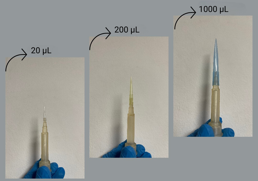
Tip holder with p20, p200 and p1000 tips.
This tip-holder design elliminates the need for switching pipettes across volume ranges, speeding up workflows and reducing risks by avoiding unnecesary tool-change operations for all pipetting work.
It does not, however, have a tip ejector yet, which is why we needed a tip ejector post.
Info
To learn more about Pipettin holder visit this page.
To learn more about 3D printing with resin and more visit this page.
Specifications
- Channels: 1
- Tip ejector: external.
- Range: 2 uL to 1000 uL (with the appropriate tip).
- Up to 0.2 uL transfers are possible, but this range is yet untested.
- Volumetric error:
- Standard model (0.7 um step): ± 0.5 uL (typical for water, systematic + random).
- Chemical compatibility:
- Limited by the tip holder material: polypropylene, acetal, etc.
- Limited by o-ring material: nitrile, viton, etc.
- Temperature compatibility:
- Room temperature (CNPT).
Safety Precautions
This is an automatic micropipette, with a relatively strong linear actuator. Avoid putting your hands or fingers into it's mechanisms while it is active.
Avoid touching it with your bare hands when cleaning it, as it may be contaminated with the samples it handled.
Be careful not to overfill the tip, as this can cause liquid to contaminate the pipette, and leak out or damage the seals later on.
Assembly
Stepwise guide
A nice and updated step-by-step guide for the assembly is available:
Instructions below can be considered development notes.
Step 1: Gather parts
Gather parts, materials, and tools from the bill of materials page.
Step 2: Tip ejector
Follow the ejection post assembly guide.
Step 3: Micropipette
Follow the step-wise guide:
Manufacturing
As explained in the Tip Holder StepWise guide there are several ways to get a tip holder manufactured. See the notes on "DIY vs BUY" there.
Technical drawings for the tip holder and CAD models are available through GitLab:
- CAD: https://gitlab.com/open-la/pipettin-bot/-/tree/master/models/MK3/tools/pmulti-MK1/pipette
- Drawings: https://gitlab.com/open-la/pipettin-bot/-/tree/master/drawings/MK3/tools/pmulti-MK1/pipette
Versions
There are two main versions, differing in the seal they use:
- Basic: Single metric 6x2 o-ring, preloaded with a 3D-printed shim.
- Advanced: PTFE seal, preloaded with 007 o-ring (ID: 6.07, CS: 1.78, OD: 9.525).
Here we show only the "plain" o-ring version, which has been tested to work well. To learn more about these o-rings, read this.
Both versions use the same tip holder and Dowel pin.
TODO
Instructions to manufacture the PTFE seal are unfinished.
Installation
Follow the remaining step-wise guides for this tool:
Interactions
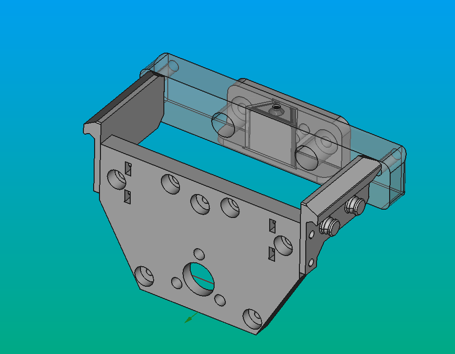
Pipettin bots micropipette tool interacts with the rest of the robot through the PIP-TRI-PLATE (green), which is attached to the HEAD_PLATE (pink) piece belonging to the tool-changer system.
The latter, in addition to being part of the tool-changer system, is also attached to the 20x40 V profile of the Z-axis of the Motion System.
Warning
Images below are illustrative, and show older versions of the pipette.
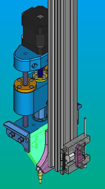
It also interacts with the Tool Parking system through the two pieces PIP-RIGHT-SUPP and PIP-LEFT-SUPP (green), which are designed to rest on the hex cap screws (red) attached to the PIP-PARK-HOLDER piece belonging to the Tool Parking system
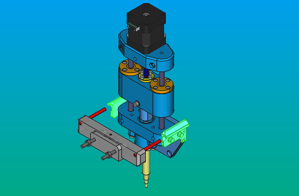
The PIP-6D-SHEAT.V1 piece interacts with the tip ejector and the racks. The tip ejector, as its name suggests, is responsible for ejecting the used tips.
Subsequently, in both the tube racks and tip racks, it manages to retrieve liquid from the tubes and also grab the tips.
Maintenance
Warning
Documentation incomplete.
Punteo para escribir:
- Cada cuanto calibrar de nuevo. Protocolo corto de calibración gravimétrica (3 volumenes, 3 puntos, etc.).
The general considerations for the maintenance of the pipette are the following:
- Check that the screws and nuts are properly tightened, as the vibration and movements of the machine can cause a slight misalignment over time and with the use it receives.
- The pipette axes must be well lubricated for its proper movement. This lubrication can be performed every few months, depending on the amount of use the machine receives.
- Ensure that no chemicals come into contact with the PLA material used for 3D printing, as it may be damaged.
- The pipette's shaft may benefit from a small amount of grease, which hel prevent gas leaks. The grease must be chemichally compatible with the material of the internal o-rings.
- The inside of the tip holder and the pipette's shaft may become contaminated or dirty due to liquids entering the tip holder's chamber accidentally. Dissasemble the tip holder and inspect if you come across pipetting issues.
- The tip holder will wear over its use, degrading or changing the fit with tips. A replacement tip holder should be installed if tips no longer seal correctly against it.
Seal maintenance
Warning
Draft documentation.
The guidelines for the maintenance for the O-ring are:
-
Clean the O-ring surfaces and pipette components regularly to remove any residue or contaminants that may compromise the seal. Use mild solvents or cleaning solutions compatible with the pipette materials.
-
Conduct periodic visual inspections of the O-ring for signs of wear, cracks, or any damage. If any issues are detected, promptly replace the O-ring to maintain a reliable seal.
-
If the O-ring exhibits significant wear, loss of elasticity, or any other issues, replace it promptly. Worn O-rings can compromise the seal and affect pipette accuracy.
Tip holder maintenance
Warning
Draft documentation.
Regular maintenance of a resin tip holder depends on factors such as usage frequency, the type of resin used, and environmental conditions. You must consider the following guidelines:
- Clean the tip holder regularly to remove any residue, dust, or contaminants. Use a soft cloth or a swab dampened with a mild cleaner.
- Periodically inspect the resin tip holder for cracks, wear, or any signs of deterioration. If issues are found, consider repairing or replacing the tip holder.
- Avoid exposing the tip holder to harsh chemicals that may damage the resin. If contact with chemicals occurs, clean it immediately and check for any damage.
- Store the tip holder in a clean, dry place when not in use. Avoid extreme temperature or humidity conditions that could affect the integrity of the resin.
- Protect the tip holder from impacts or falls that may cause damage. Depending on the type of resin, it may be susceptible to breakage or chipping upon impact.
- If you notice significant deterioration in the resin of the tip holder, consider repairing or replacing it to maintain optimal performance.
Design
Warning
Documentation not yet available.
Punteo para escribir: - Bajar todo lo que está acá: https://docs.google.com/document/d/1hw5rCYd1IgkT0JHzXOWHoYqA7-mOKWN2VWKn604YDEY/edit - Revisar el resto: https://drive.google.com/drive/u/0/folders/13IvH6O6TlzW5Bn8h7awG7k17kan-00aA - Revisar el Trello (tiene issues viejos): https://trello.com/b/FM7SVfnb/pipettin-bot-pipetas
The "dead volume" is the volume of air contained between the piston chamber and the tip's tip.
The dead volume must be minimize in order to maximize the pressure change generated by the displacement of the pipette's internal piston. If the "air gap" is larger, the pressure differential its movemement generates will be lower, and this will increase the effect of deviations due to water column weight or capilarity (read on).
In the extreme, a null dead volume is equivalent to a positive displacement micropipette (the piston is disposable on those).
The only dead volume we can minimize in an air-displacement micropipette is the one inside the pipette. Other pipettes reduce the dead volume inside the tip by having a shaft that extends ouf of the tip holder, and into the tip, on its lower positions.
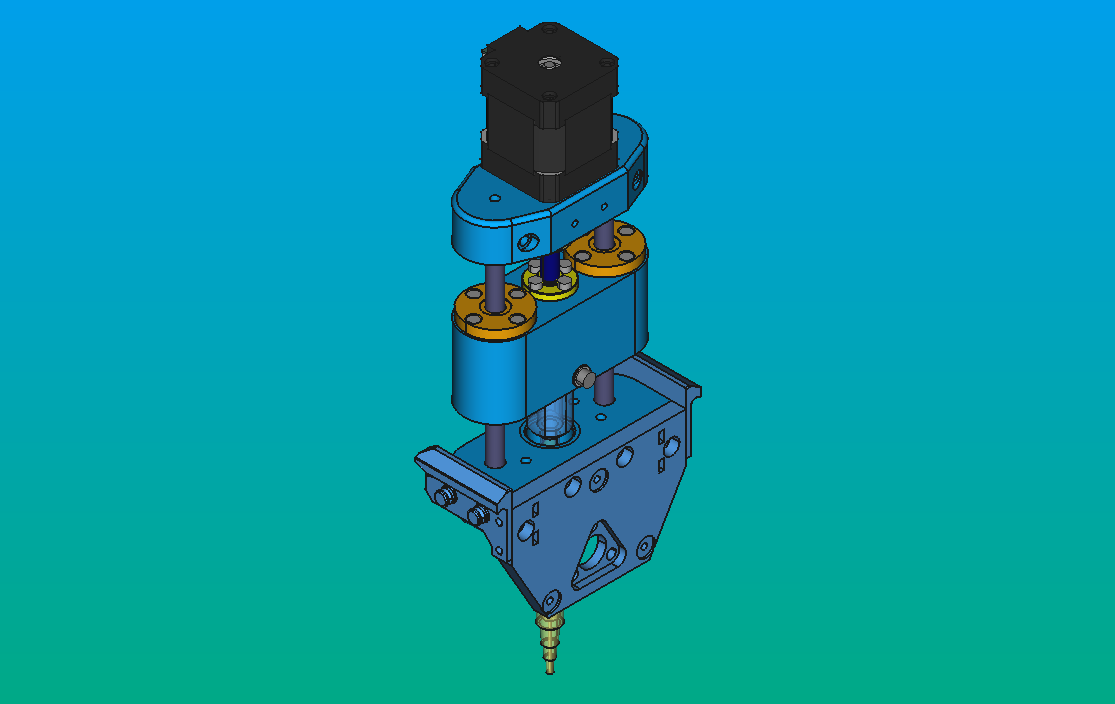
Previous versions
There is an older but almost identical version of the pipette, originally designed by Bruno and ported to FreeCAD by Agustín.
It was re-designed for compactness, and to reuse the carriage design from the pipette adapter tool.
Models
Links to CAD files listed in the sources page.
Legacy models:
- Old models: https://drive.google.com/drive/u/1/folders/1Y6QIhQA8oujrZLix_5DpmFptjIccoLtv
- Even older models: https://drive.google.com/drive/u/1/folders/17gNf42ngrqhPh287f35ruqajgMG8ZHUc
- Deprecated models: https://gitlab.com/open-la/pipettin-bot/-/tree/master/models/modelos_tools/pipetas_bruno
Development
These 3D-printed parts were designed in FreeCAD 1.0, and saved in the native FCStd format. Printable STL files were printed on an Original Prusa i3 MK3.
To learn more about these file formats visit here.