Motion System
Motion System
Info
Discord forum thread: Motion System License: CERN-OHL-S-2.0
Overview
The motion system of the Pipettin Bot consist in a few motors, pulleys, and belts to achieve motion in 3 cartesian axes (i.e. X, Y, and Z).
The motion system is divided in 2 parts, with 3 linear actuators in total. There is the "XY Axes Linear Actuator", and then the "Z Axis Linear Actuator", mounted on top.
Throughout this section you will find general guidelines for building the Pipettin Bot's motion system, such as it's drawings, assembly instructions, and other options you could consider.
Usage
The motion of the robot can be manually controlled through GCODE or nicer frontends, such as Mainsail (referred to as "the joystick" elsewhere).
Danger
Do not move/touch any linear actuator while the robot its working or it can cause an injury to the user, damage the robot, or cause mis-calibration.
This last issue may not be apparent at first sight, but must be checked after a crash.
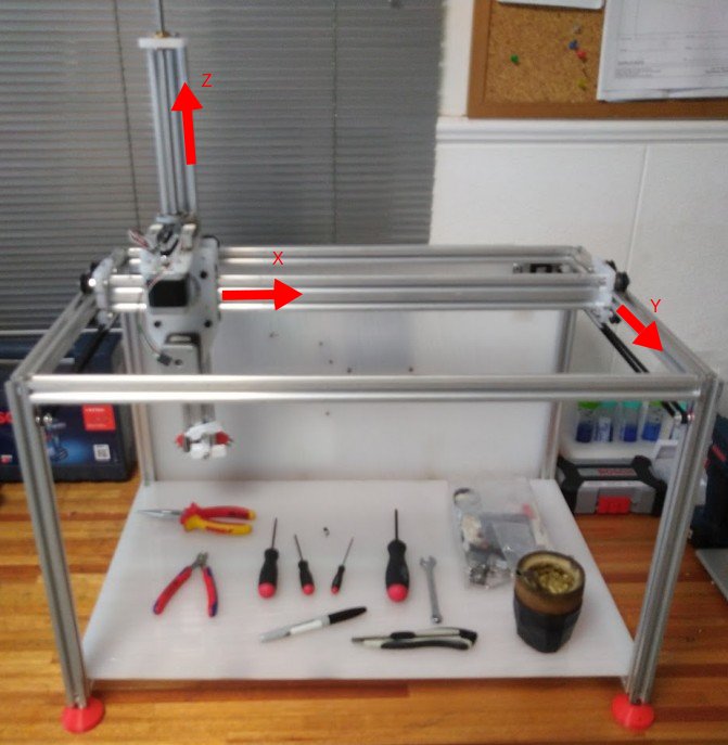
Motion system with the GT2 transmission belts on, mounted on the structural frame. Note that it's coordinate system follows a left-hand rule, which is heresy, but we can blame frontend developers for that :P.
Assembly
Note
The motion system is mounted on top of the Structural Frame.
Make one first if haven't  .
.
Stepwise guide
A nice and updated step-by-step guide for the assembly is available:
Instructions below can be considered development notes.
Manufacturing
Preamble
The motion system has two basic structures: the XY-Axes actuators, and the Z-Axis actuator.
The following links point to the assembly guides for each one, and they will be referred to when relevant in the instructions below.
Tip
We recommend building the XY-axes first, followed by the Z-axis. See instructions below.
Step 1: Gather all the motion system parts
Parts, materials, and tools can be found in the bill of materials page.
Step 2: Profile Machining Instructions
Instructions:
- Follow the XY-Axes Machining Instructions
- Follow the Z-Axis Machining Instructions
Step 3: Assemble the structure
Instructions:
Interactions
As mentioned before, Pipettin Bot's motion system consists of two linear actuators: the XY-axes linear actuator and the Z-axis linear actuator.
The XY-axes linear actuator functions as a guide and support platform for the X-axis carriage. The X-axis carriage is responsible for movement along the X-axis.
The Z-axis linear actuator is fitted to the X-axis carriage. It is responsible for maintaining the positioning of tools and providing movement along the Z-axis. The Z-axis also provides movement for the tools, which are connected to the Tool-changer.
For movement along the Y-axis, the actuator is attached to the structure using Y-axis carriages. These carriages are supported by the upper profiles of the Structure and connected to the actuator via brackets attached to each end of the actuator profile.
Maintenance
Keeping the the motion system clean and lubricated is critical, to ensure the proper functionality of its moving parts. Failure to do so may result in motion errors or crashes.
If any 3D-printed components are broken or deformed, they must be reprinted and installed.
Regularly, you may assess the condition of the timing belts: check for correct belt tension, wear, and potential damage.
Also, the pulleys should be clean, aligned, and free to rotate smoothly. Replace or fix pulleys that show issues to prevent accidents.
The brushless stepper motors do not require maintenance mid-term. It's ok if they feel warm but not unbearably hot to the touch while functioning.
Design
You can assembly the motion system's parts independently of the others. However, you need to have the correct measurements of the structure to be able to mount it to the structural frame later. We recommend to follow the steps in the order that appears in the assembly guide.
The motion system is connected to the rest of the robot through its joints with the Y-carriages. In turn, this connects the XZ-axes to the robot.
It uses a 20x40 V-slot extrusion as a linear rail, but it can be made with a pair of 20x20 extrusions, joined side-by-side with several screws and nuts along its length.
Previous versions
The previous version of the robot (Pipettin Bot V1) employed tempered rods as axes to facilitate its movements.
The vertical axis of this setup exhibited excessive wobbling, which hindered precise movement. We think that the following factors might have caused this issue:
- The use of LM8UU bearings with lots of play.
- The use of long tempered rods, which are rather flexible.
We also analyzed the possibility of adding a third tempered rod, to eliminate one degree of freedom. However, we finally leaned towards a complete redesign.
We decided to replace the rods with aluminium extrusions. These profiles are also cheaper an easier to source.
The position of the tool-changer motor added other factor to increase the instability. It acted as a pendulum. For this, we redesigned the Tool-changer mechanism.
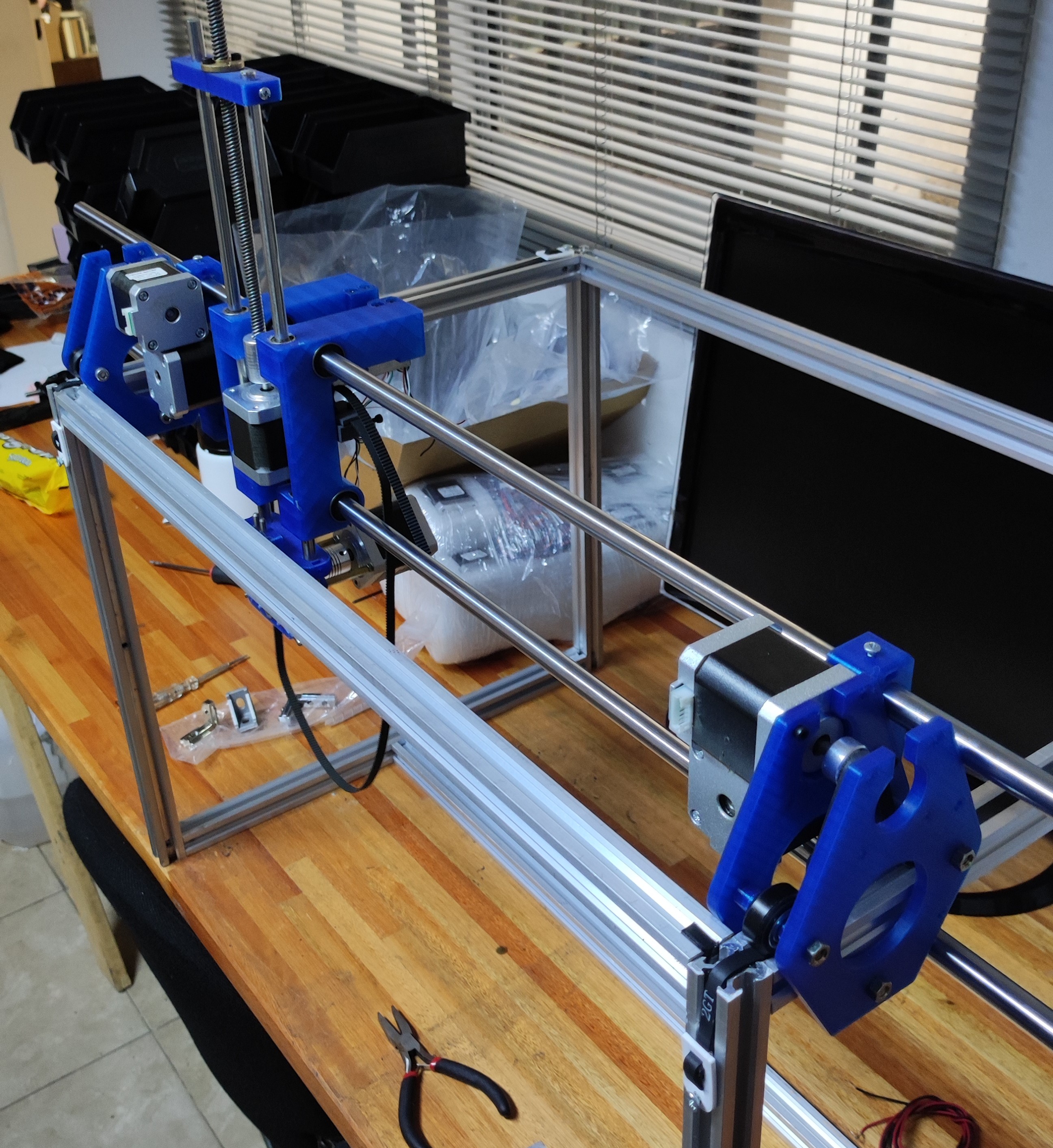
The design of the previous X-axis incorporated a single stepper motor and a pulley, both of which are oriented perpendicular to the profile on the X-axis. The brackets were carefully designed to fit the dimensions of the GT2 16T pulley.
Initially, we attempted to create a model using a lone bracket for the motor and another for the pulley. These brackets had a width of 10 mm to fit both the pulley and the motor, and a width of 3 mm to match the 20x40 V profile. However, upon printing and assembling them, it became evident that these models lacked the required strength and rigidity necessary to effectively support the overall structure.
Fractured parts:
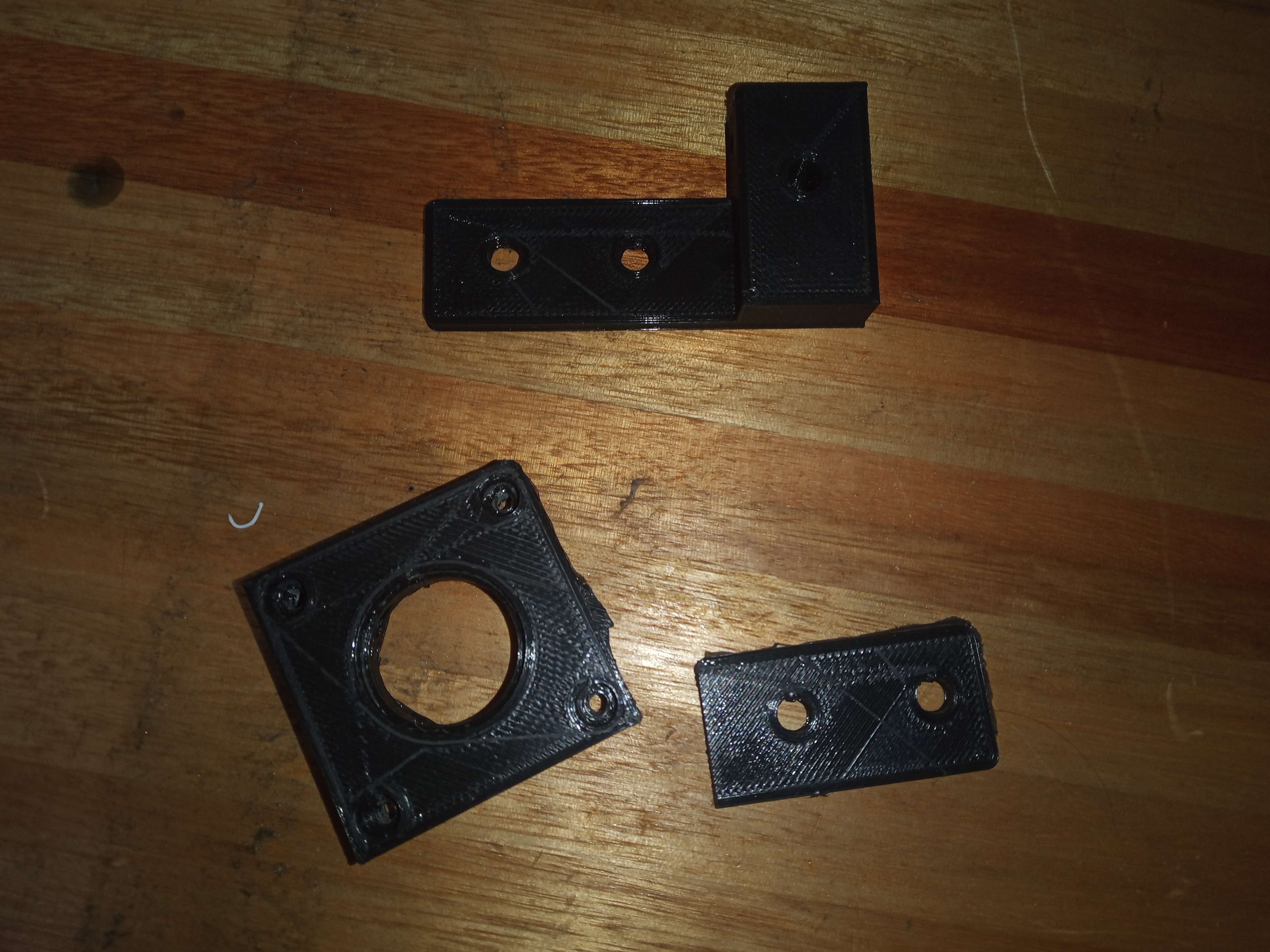
To enhance the rigidity and durability of the brackets, a decision was made to increase their width to a consistent 10 mm. Additionally, an identical extra piece was incorporated to each grip, enabling them to provide support to the 20x40 V profile from both sides.
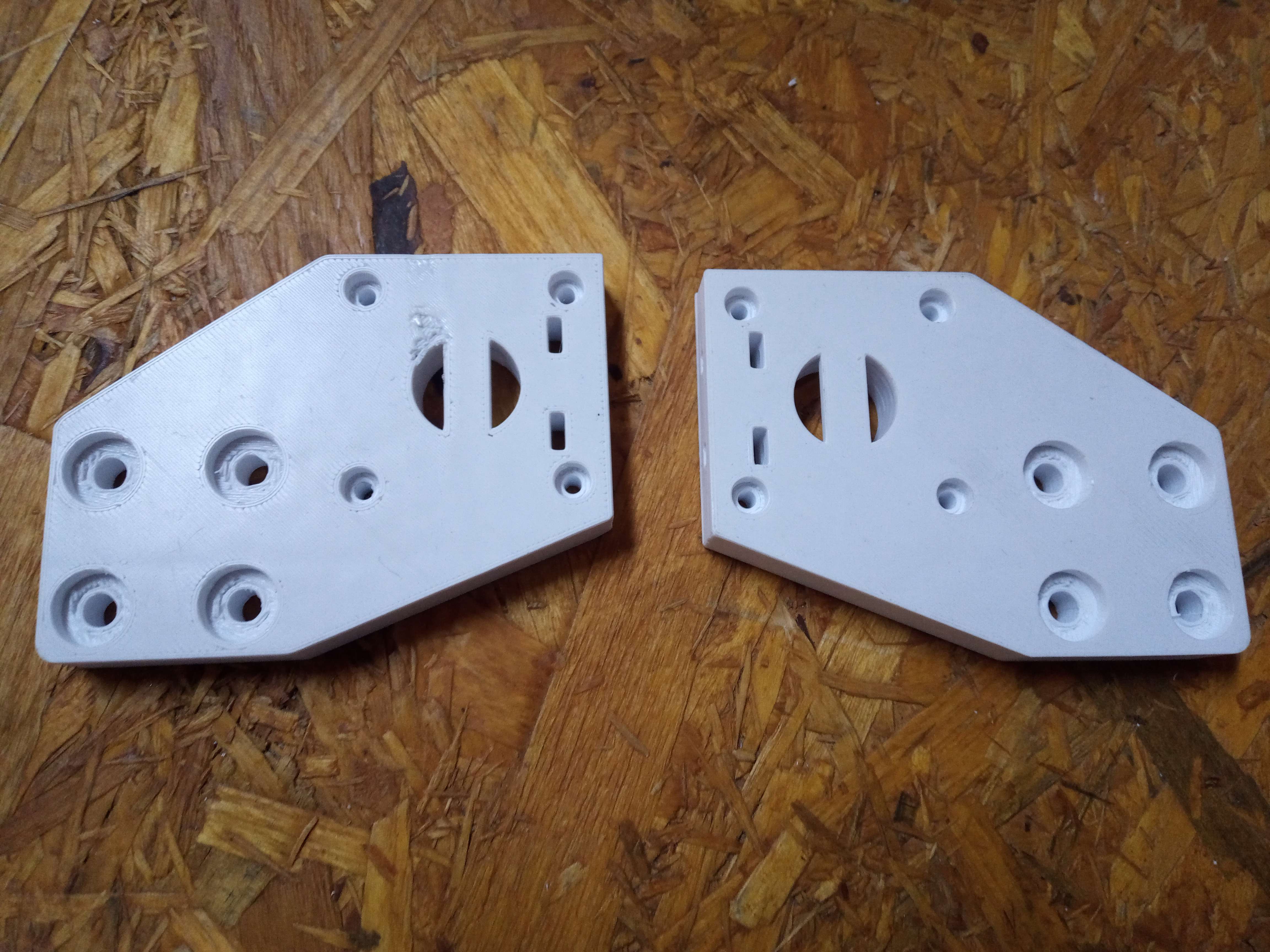
The pieces were designed using FreeCAD, with the intention of optimizing them for 3D printing. This approach was chosen due to its cost-effectiveness and the convenience it offers in terms of making edits based on your robot's requirements.
Models
Links to CAD files listed in the sources page.
Development
These 3D-printed parts were designed in FreeCAD 1.0, and saved in the native FCStd format. Printable STL files were printed on an Original Prusa i3 MK3.
To learn more about these file formats visit here.