Articulated Feet
Articulated Feet
This page is dedicated to making "feet", to provide better support for aluminium extrusion structures.
Overview
Articulated feet can be added to a machine's structure.
This has the following advantages:
- Tolerate irregularities on the supporting surface.
- Elevate the structure from the surface.
- Allows leveling and preventing wobbling.
Usage
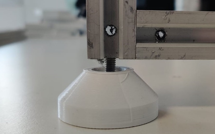
Each leg needs to be attached to the support structure on the tapped end of a profile, on a V-slot nut, or equivalent.
To adjust its height, turn the screw from below the feet.
Caveats and Limitations
Height can't be adjusted if the articulated foot is attached to a V-slot nut, as those have very limited travel, and need to be fully tightened to prevent wobbling.
Assembly
Expected result:
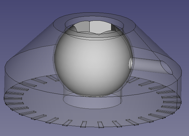
The rotulas are "printed in place". This requires adding a small amount of support material during 3D-printing.
Steps:
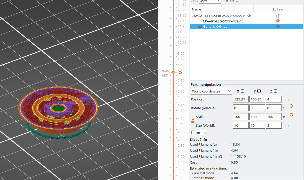
- Print 4 articulated legs, adding a small and short support in the center.
- Note that the support must not be "tall", to avoid filling the hole on the side.
- Note that they are printed "upside down".
- Adding a brim might help with bed adhesion.
- CAD files are here.
- Remove the support and brim (if used).
- To assemble the rotula, find an M5 screw and its nut.
- Optional: find a second M5 nut, which can later be used to tighten the screw against the profile. This will keep the feet from unscrewing themselves.
- Screw the rotulas to the bottom of each vertical profile (n=4).
- To hold it in place while doing this, insert a small hex key from the side, using the horizontal hole (it's there only for this purpose).
- Optional: add a second M5 nut to the screw, but don't tighten it.
- This completes the basic assembly of a foot.
Installation
- Screw the foot to the end of a profile, which must be already tapped with an M5 thread.
- Use a spirit level to level the structure above by turning the screws of the appropriate feet.
- Optional: tighten the second nut against the profile, which will secure the foot in place.
Interactions
The feet interact with:
- The supporting surface for the machine (e.g. a table).
- M5 threads on the structure's vertical 2020 profiles, in V-slot nuts, or equivalent.
Maintenance
No special maintenance is required.
If the second nut is not tightened against the profile, you may need to check your leveling every now and then.
Design
This piece was designed as a simple and cheap replacement of commercial "articulated legs".
It is easy to manufacture and replace.
Models
FreeCAD files: