Centrifuge
Taperfuga: portable BLDC Centrifuge for field work
A barebones, portable, tupergüare-style centrifuge for field work.
It's awesome:
Overview:

Originally designed for the reGOSH 2023 libre-tech residency in Chile: https://luherbert.gitlab.io/wiki-regosh-2023/hardware/taper-fuga/Centrifuge/
Video teaser
Watch our video at YouTube: https://www.youtube.com/watch?v=Lnsp6m0MHxk
Features and Caveats
Features:
- Portable: uses a small LiPo battery for power, can be carried in a backpack (even while running), upwards, sideways, or upside-down.
- It's cool:
- Swing-bucket style rotor.
- Uses a BLDC from an old HDD.
- Optionally refrigertaed (put it in a fridge!).
- Fast-ish: at least 3000 rpm, probably 6000 rpm or more.
Caveats:
- Not so low-cost: you can make a centrifuge with less complicated motors (e.g. DC motor instead of a BLDC motor) and controllers (i.e. simple MOSFET circuit, instead of an ESC module).
Assembly
Step 1: gather parts
Parts and materials:
- 10 cm wire
- 3 Crocodile clip / connectors
- M3 screws and nuts.
- 11.1V Li-po battery (3S).
- ESC for BLDC motors.
- A suitable plastic container with lid (a.k.a. a "tupper").
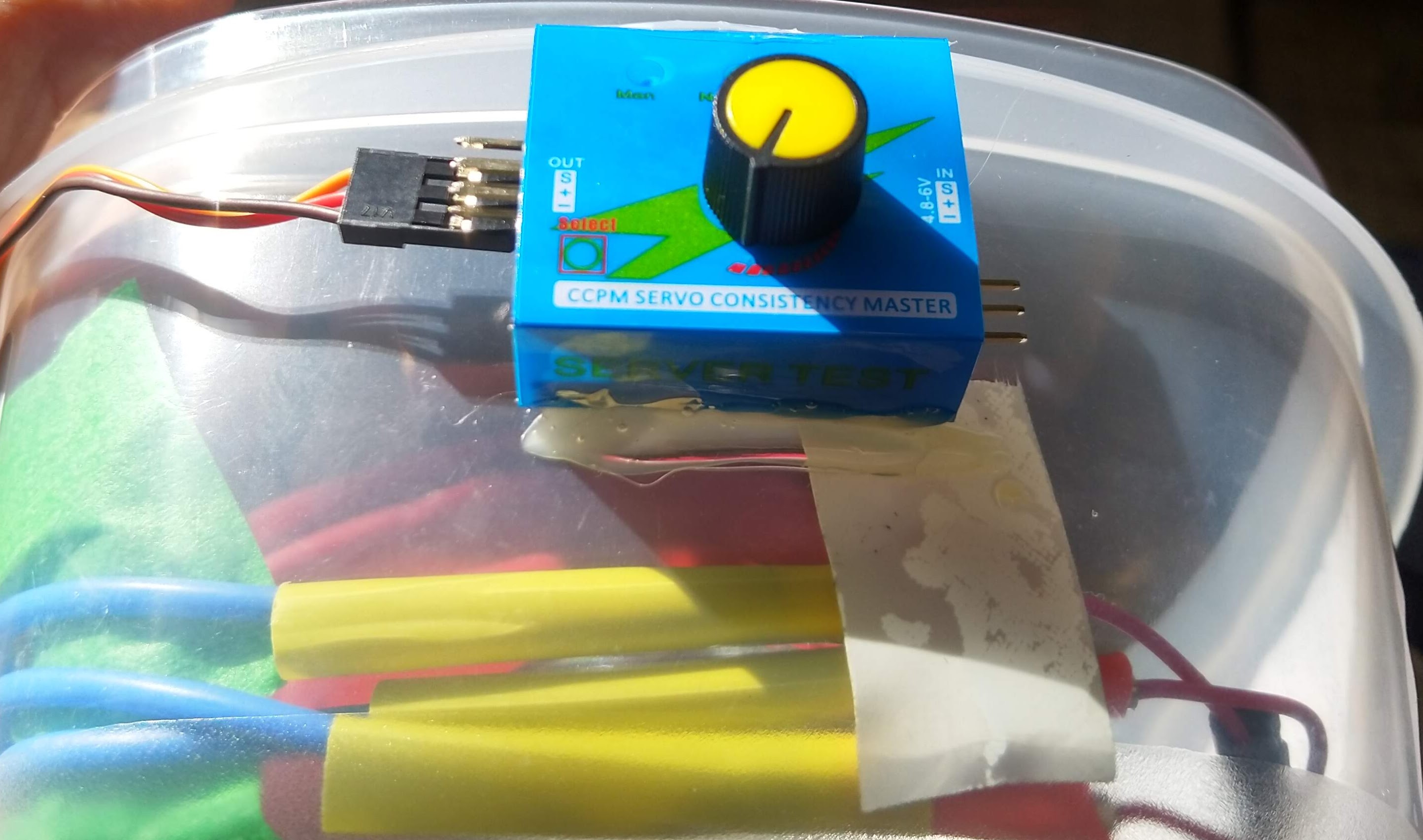
- Servo tester.
- Plastic foam (e.g. polyethylene foam).
- BLDC motor, either from a discarded HDD or a drone/UAV motor.
Tools for assembly:
- Soldering iron.
- M3 tap and electric drill.
- Double-sided and electrical tape.
- Screwdrivers, M2.5 and M3 hex keys, pliers.
- Multimeter.
- Hot glue gun.
- 3D-printer.
Step 2: get a motor
- Solder wires to each copper pad.
- If you are reusing a BLDC motor from an old HDD with 4 wires, use a multimeter to find the wire corresponding to the "star point", this wire won't be used. Solder "crocodile clips" or other suitable connectors to the ends of the three phase wires.
- If you are reusing a BLDC motor from an old HDD, thread it's mounting holes with an M3 tap, and attach long M3 screws to them.
BLDCs from newer HDDs cannot be separated from the aluminium base, and require heavy-duty hardware surgery for removal.
- Hot to disassemble an HDD and extract the BLDC motor: https://hackaday.com/2016/02/03/hard-drive-disassembly-is-easy-and-rewarding/
- Select and purchase a new BLDC motor: https://learn.adafruit.com/adafruit-motor-selection-guide/brushless-dc-motors
- Ask a friend if they have a spare :)
Step 3: print the rotor and purchase a container
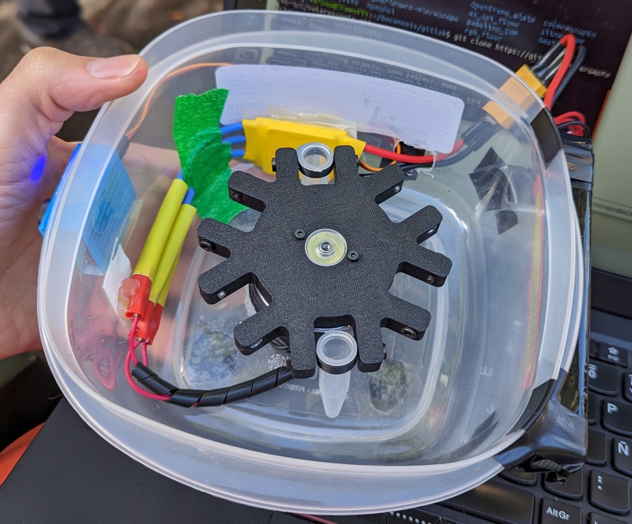
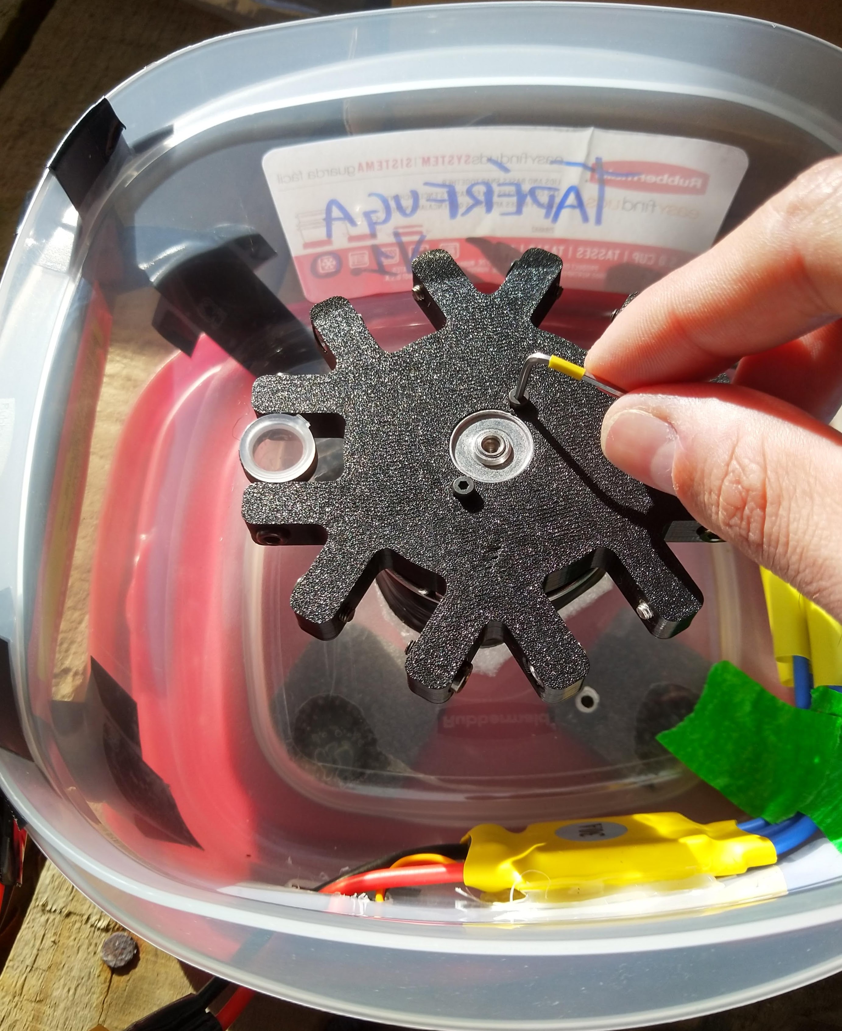
- 3D-print the rotor. Files available here. Currently only fits a BLDC motor from an old HDD.
- Insert short M3 screws into the slots, such that their threads protrude a bit into the slots. then place a "swing" for 1.5mL tubes, and place a tube in it. Adjust the screws until they block the tube's pivoting, and then release them a bit such that the tube can swing freely, but is also well supported.
- Use the rotor assembly to find a suitable plastic container. It must be wide enough to fit the rotor and the tubes when "fully swinged out".
Step 4: Attach the motor and rotor
- BLDC motors from old HDDs can have 3 mounting holes, which can be threaded with an M3 tap.
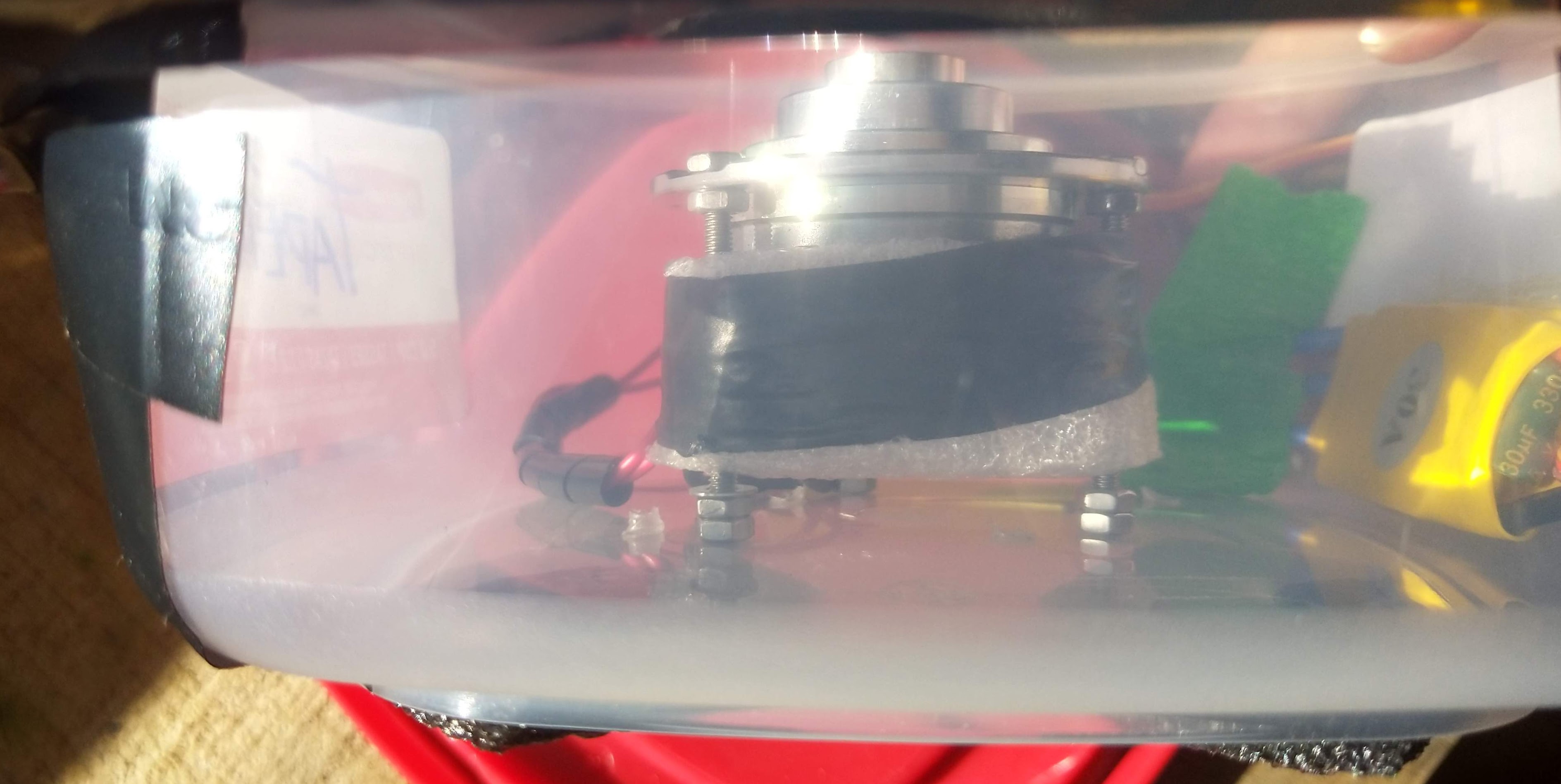
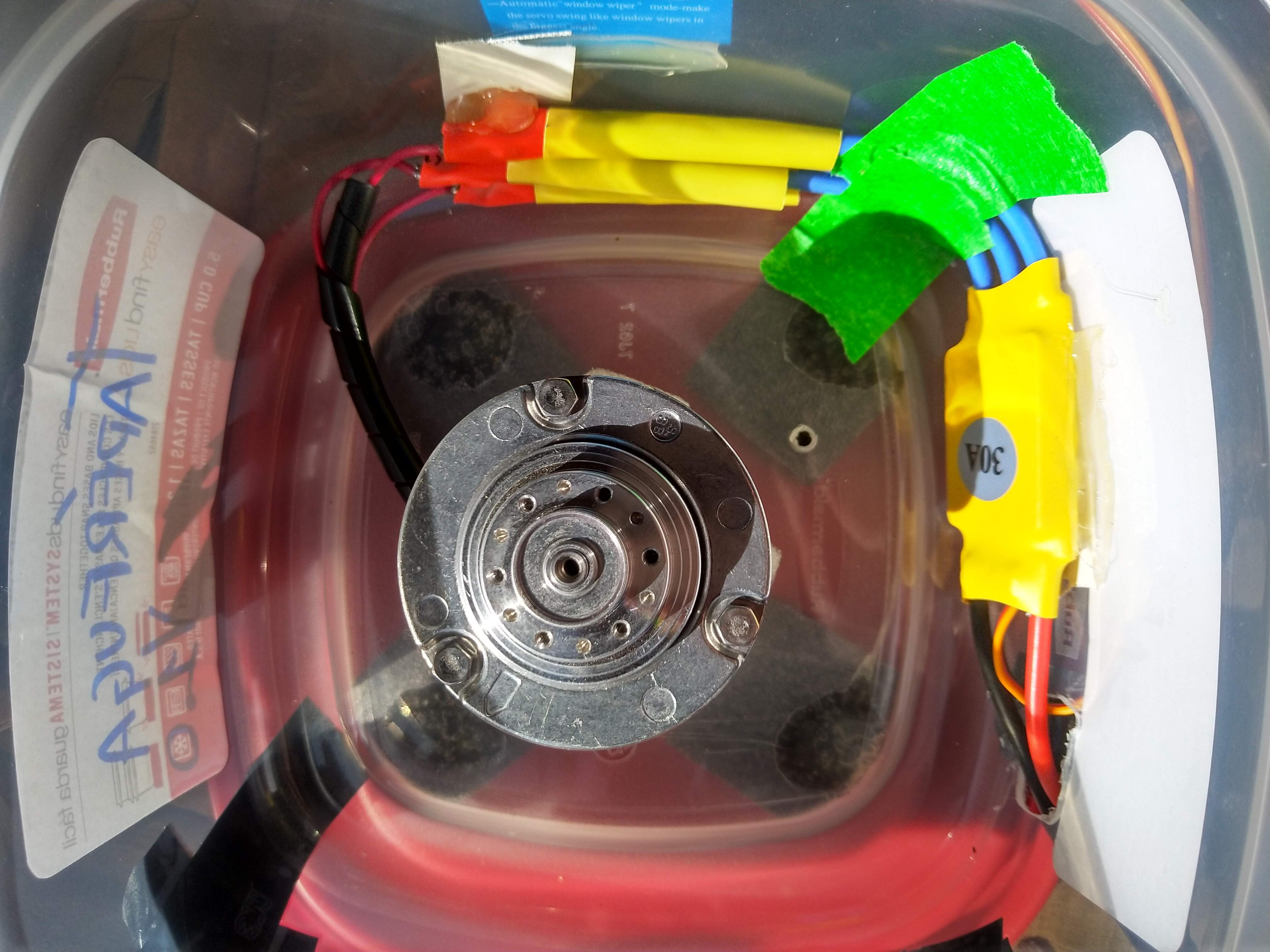
- Attach the motor to the plastic container by making holes through the bottom of the container.
- The rotor must be well centered and at a suitable height, allowing the tubes to hang and swing without colliding with the walls of the container (or other components).
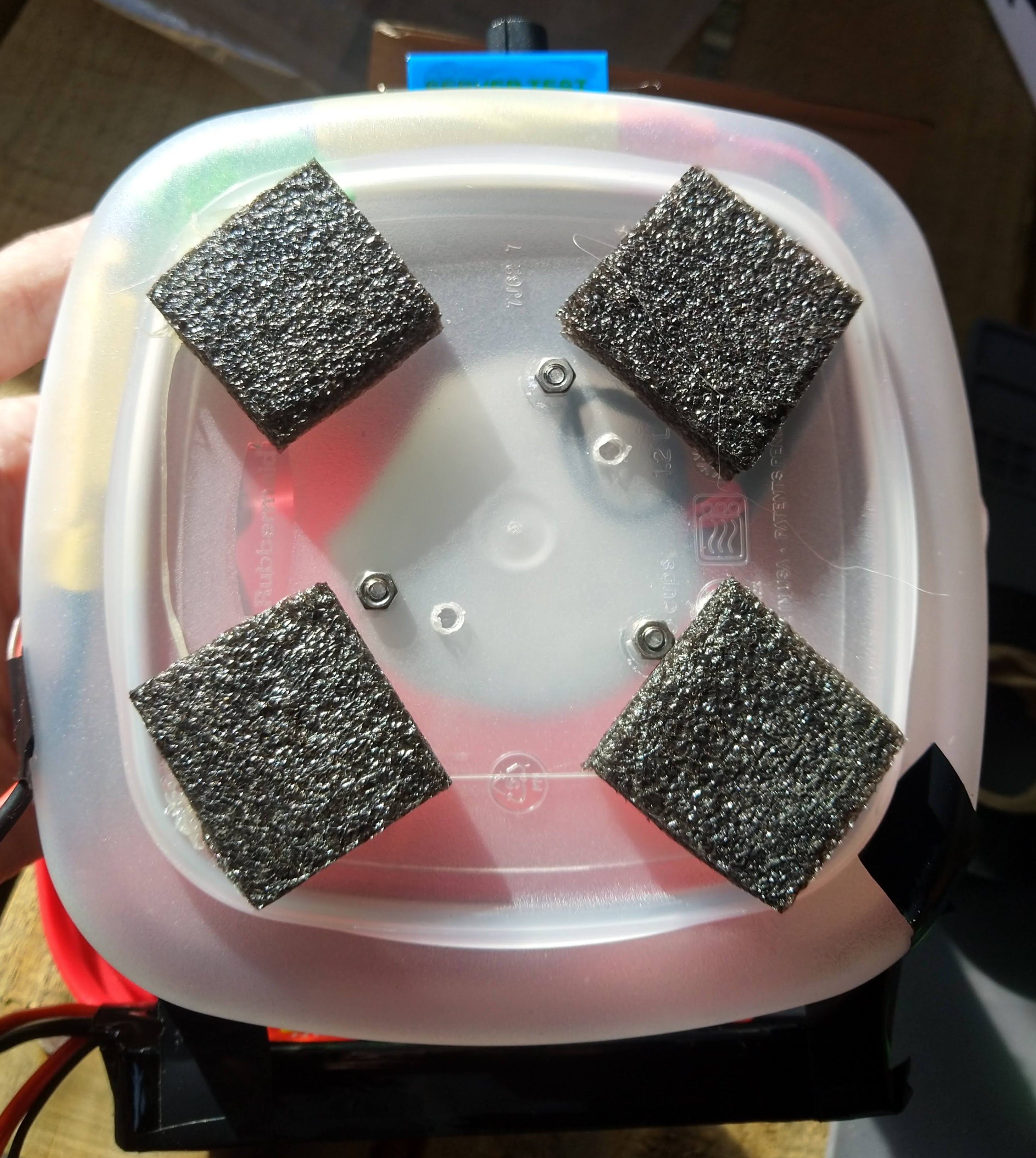
- In the picture below you can see I used a pair of nuts on each screw, which are tightened against each other to prevent the motor from sliding downwards. Three more nuts were tightened on the other side of the container's base to attach the motor firmly to it.
- Add plastic foam pads to the base of the container, using a hot glue gun.
- Attach the rotor using two M2.5 screws.
Step 5: connect the electronics
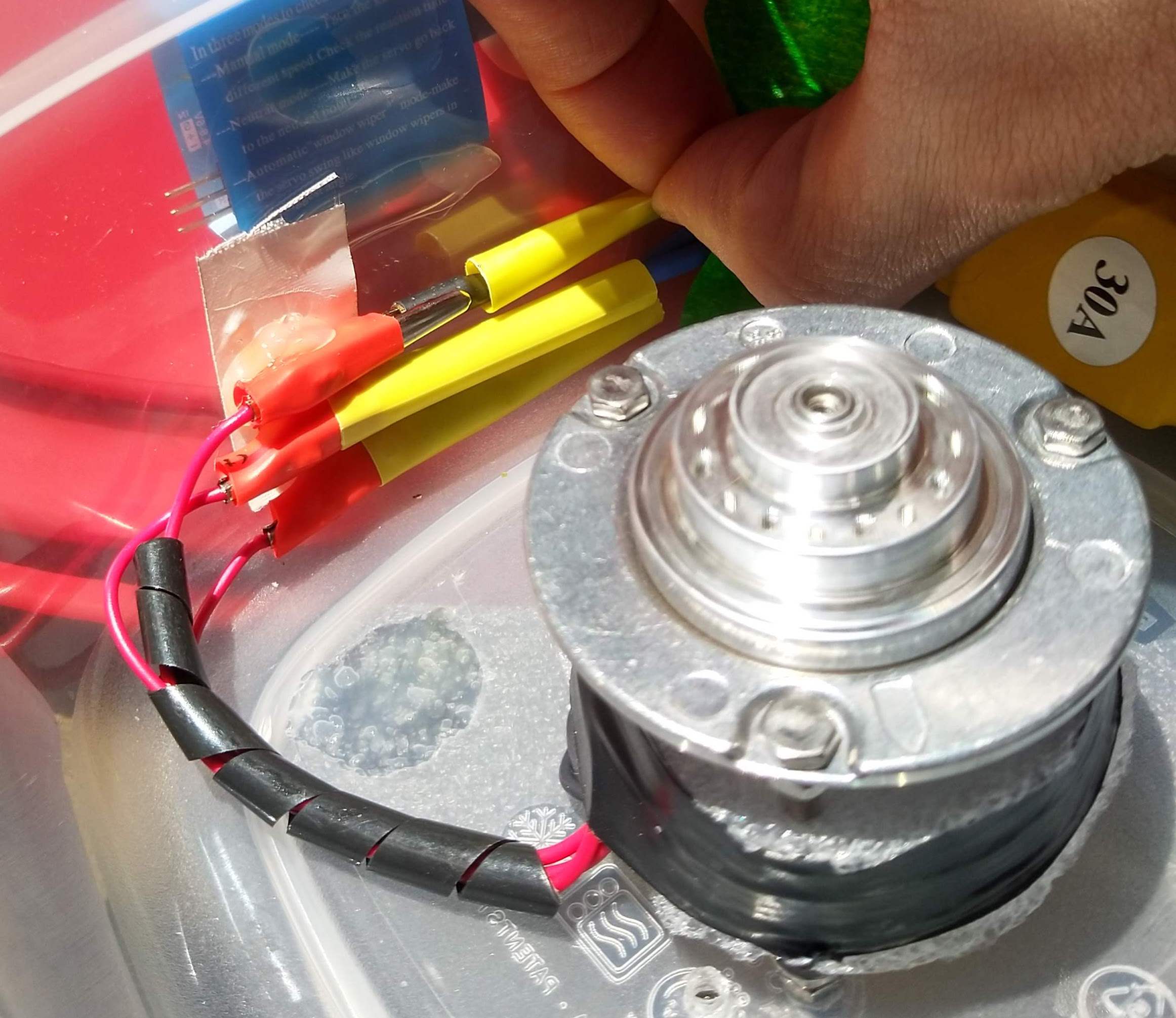
- Connect the BLDC's three phases to the ESC controller. You can isolate the ends of the crocodile clips from each other by sliding in some heat-shrink around them (without applying heat) or using some electrical tape.
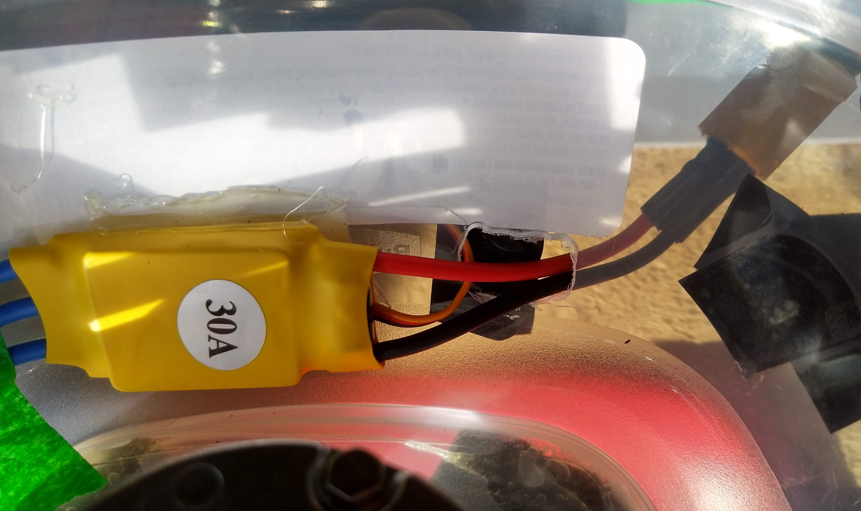
- Attach the ESC to the container's bottom, tucking everything with tape or hot glue, to prevent the tubes from hitting them when spinning and swinging.
- Make a hole through the side of the container to pass the ESC's power wires and control cable.
- Connect the control cable to the servo tester, and glue the servo tester to the outside of the container.
- Connect the battery to the ESC's power connector (there are different connectors, and you may need to swap them) and tape the battery to the outside of the container. Otherwise, solder a plug connector to the ESC and use a regular 12V power supply, capable of delivering at least 2A.
Simple FOC centrifuge
Work in progress
Work in progress: home-able BLDC centrifuge for the pipetting robot.
Initial implementation:
- BLDC motor with FOC control, using SimpleFOC:
- For positional control (either open-loop with homing or closed-loop with position sensors) to stop the centrifuge exactly where it started, thus leaving the tubes on their original positions (this is needed for a robot).
- For high-RPM cetrifugation, needed by most protocols.
- Lower maintenance motor.
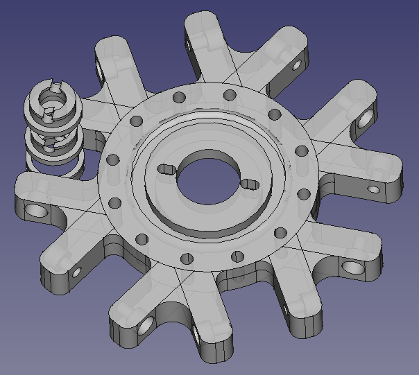
- Swing-bucket rotor, to avoid the need for rotational axes on CNC tool-heads.
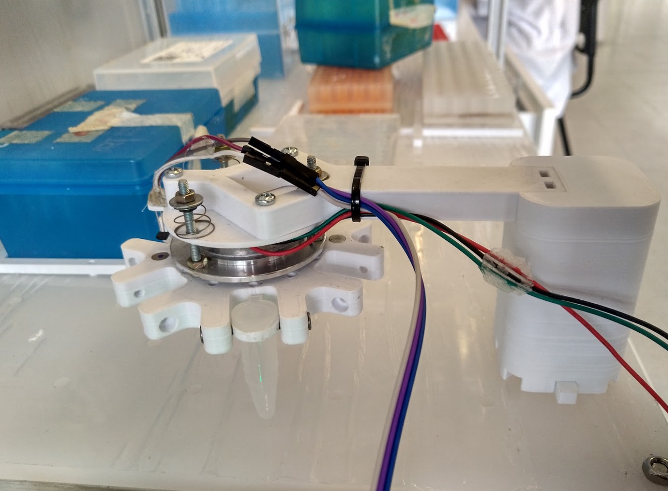
- Added small and soft springs to the buckets, ensuring they end up in vertical position.
- Note: the rotor cannot be fixed but tilted in order to get the tube vertical, because the tube on the opposite side would be horizontal.
Preview:
Salvaging BLDC motors from old HDD drives
The HDD must have a "removable" motor. Newer HDDs have non-removable motors which are more difficult to adapt. GaudiLabs' centrifuge project may be better suited to those motors.
A few videos we found helpful follow.
Salvaging a removable motor
Watch Ludic Science's video: https://www.youtube.com/watch?v=ycb6waem0HU
Making connections to an ESC controller
Watch GrcByte's video: https://www.youtube.com/watch?v=GK9z41iKcNo