Pipettin Bot Electronics
Electronics
Warning
This section is quite incomplete, but can be followed by an experienced maker. Ask for help on the Discord: Pipettin Bot Electronics
Overview
This section aims to provide comprehensive guidance on adding and controlling actuators to the structure.
This documentation provides step-by-step instructions to facilitate the understanding and replication of the robot's electronics, ensuring an open and accessible platform for users to replicate and modify the system according to their specific requirements.
Usage
The electronics are meant to be operated through graphical user interfaces, enabling users to send commands, configure parameters, and monitor the robot's operation.
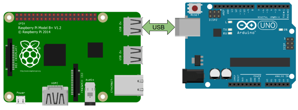
At the core of this interaction is the Raspberry Pi, serving as the robot's main computer. It serves the user interfaces and translates its commands into executable GCODE. These commands are then relayed to the CNC boards, which are dedicated to driving the stepper motors.
The CNC boards are responsible for the precise transmission of signals to the stepper motors, which are integral for the accurate and controlled movement of the robot.
Caveats and Limitations
Incorporating additional tools or accessories beyond the standard pipette, such as a hot bed, laser module, or similar devices, may necessitate modifications to other system components to ensure optimal functionality and maintain system integrity. One critical aspect to consider may be the power supply unit, for example.
The cheaper stepper motor drivers are more prone to stop functioning. Such issues might arise when the "Vref" (reference voltage) isn't adequately set to supply the required power for the stepper motor. You'll find instructions for this below. Even if respecting their maximum ratings, these drivers are a hit or miss: some of them will be good, and some of them will fail too soon.
The Duet2 WiFi can only control 5 motors. This means that a Duet-only setup will be able to use a single micropipette tool. There is an expansion board which we have not tested with Klipper (which does not recommend using the "multiplexed" IO pins to drive steppers or sense endstops). Consider adding a CNC shield to drive more tools.
Assembly
Warning
Under development!
Briefly, throughout this stage you will:
- Attach endstops, wire motors, connect the Arduino with Klipper and a CNC shield.
- Manage cables.
- Wire up the Rapsberry Pi and the remaining connections (USB and GPIO).
- Make the electronic's case.
- Assembly all the electronic components
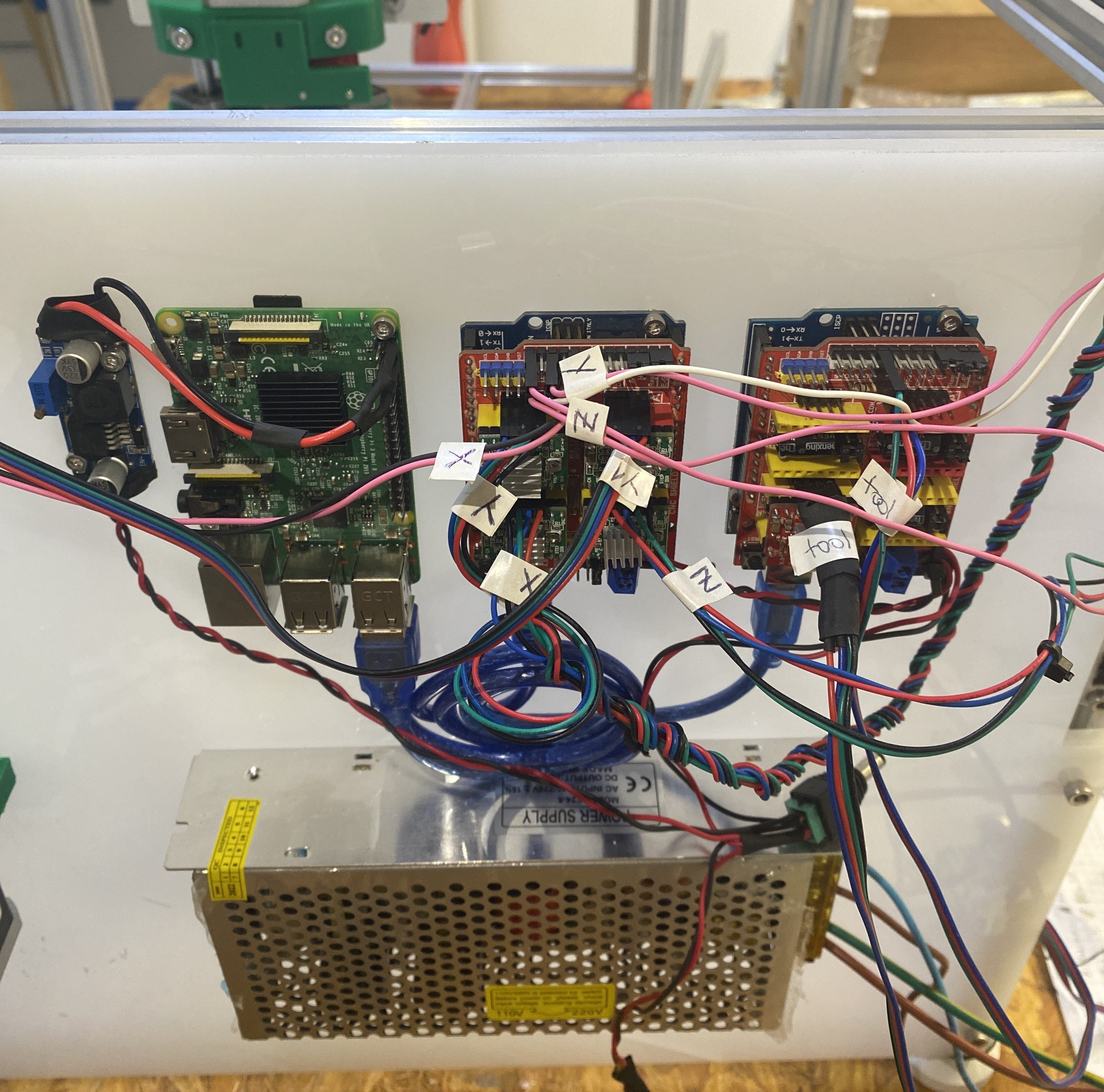
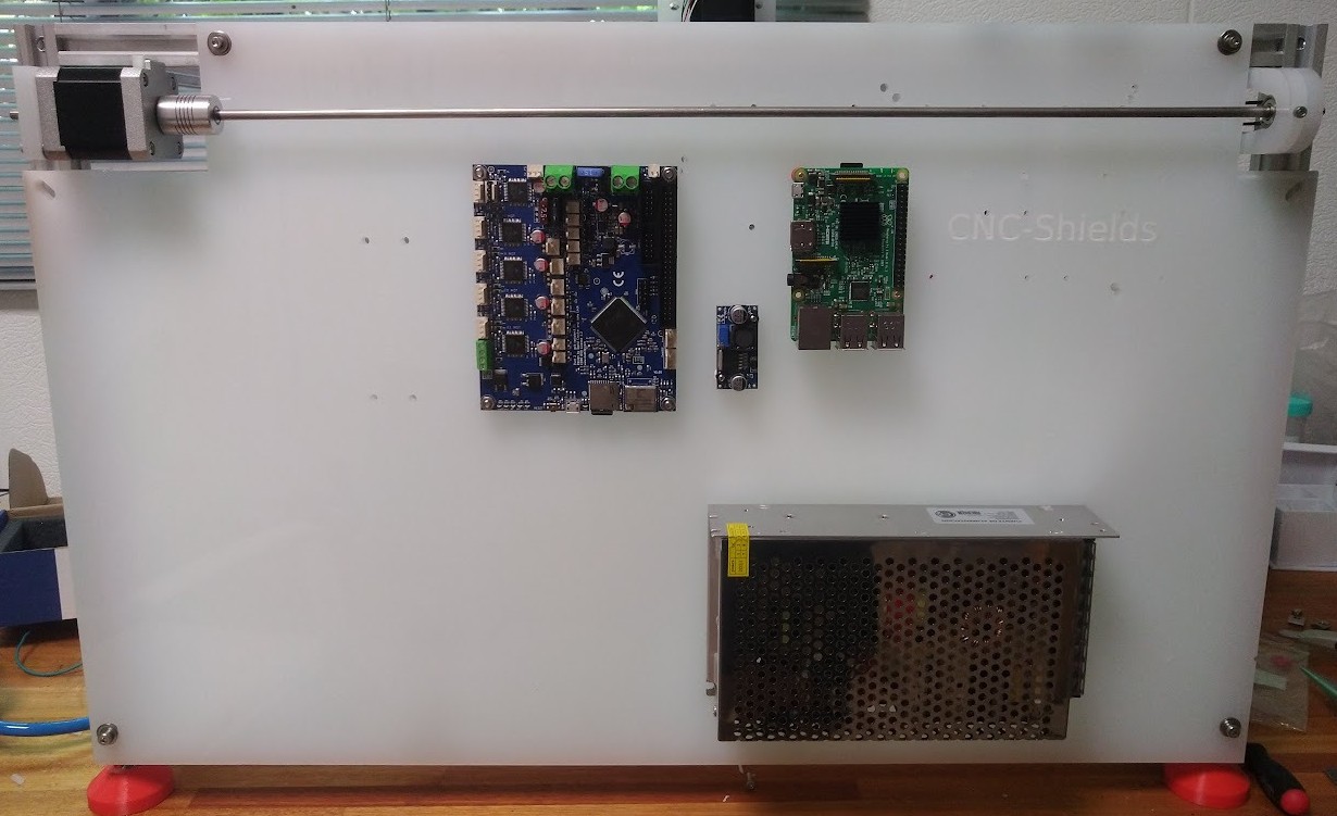
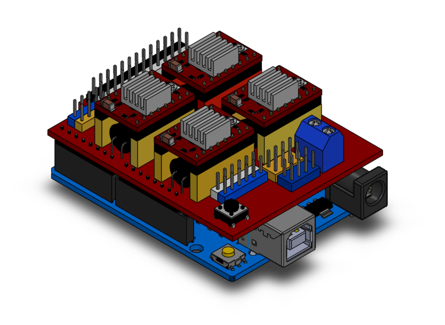
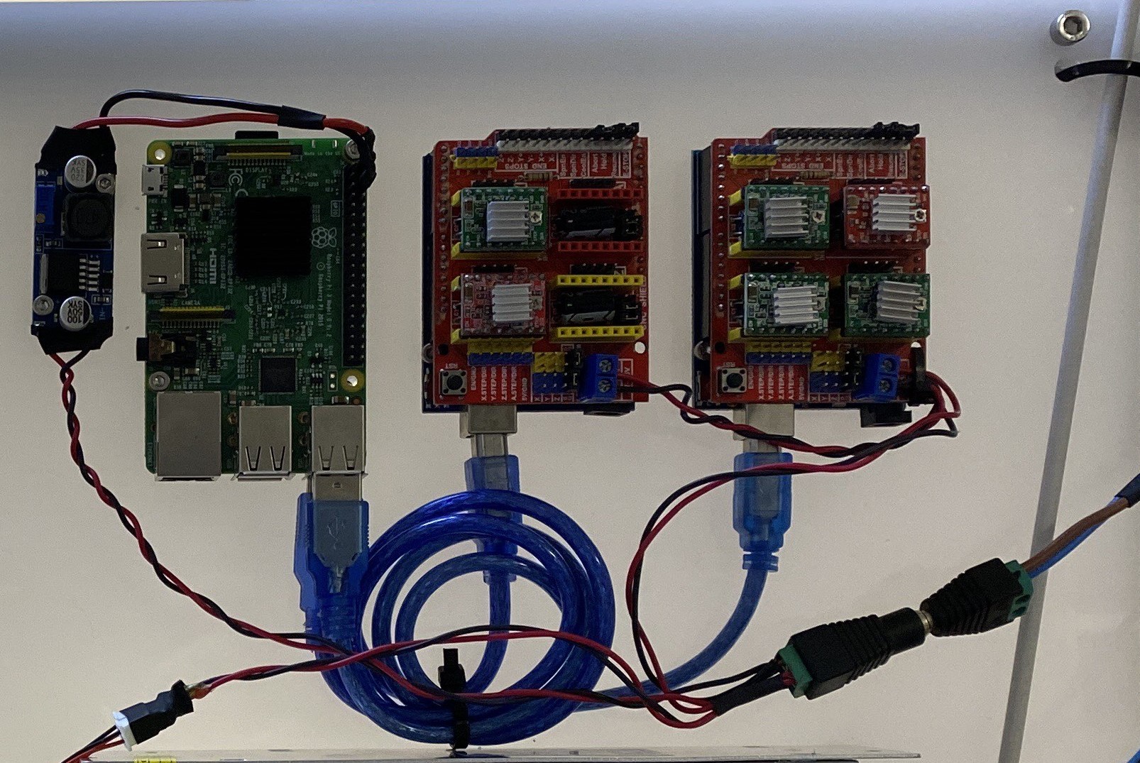
The backpanel is where all the electronic will be mounted. This version is meant to have a RPi model B (left side) and two Arduino UNO with their respective CNC shields mounted on top of them (center and right side). The sides are T-slotted, and will fir M3 screws and nuts.
Expected result:
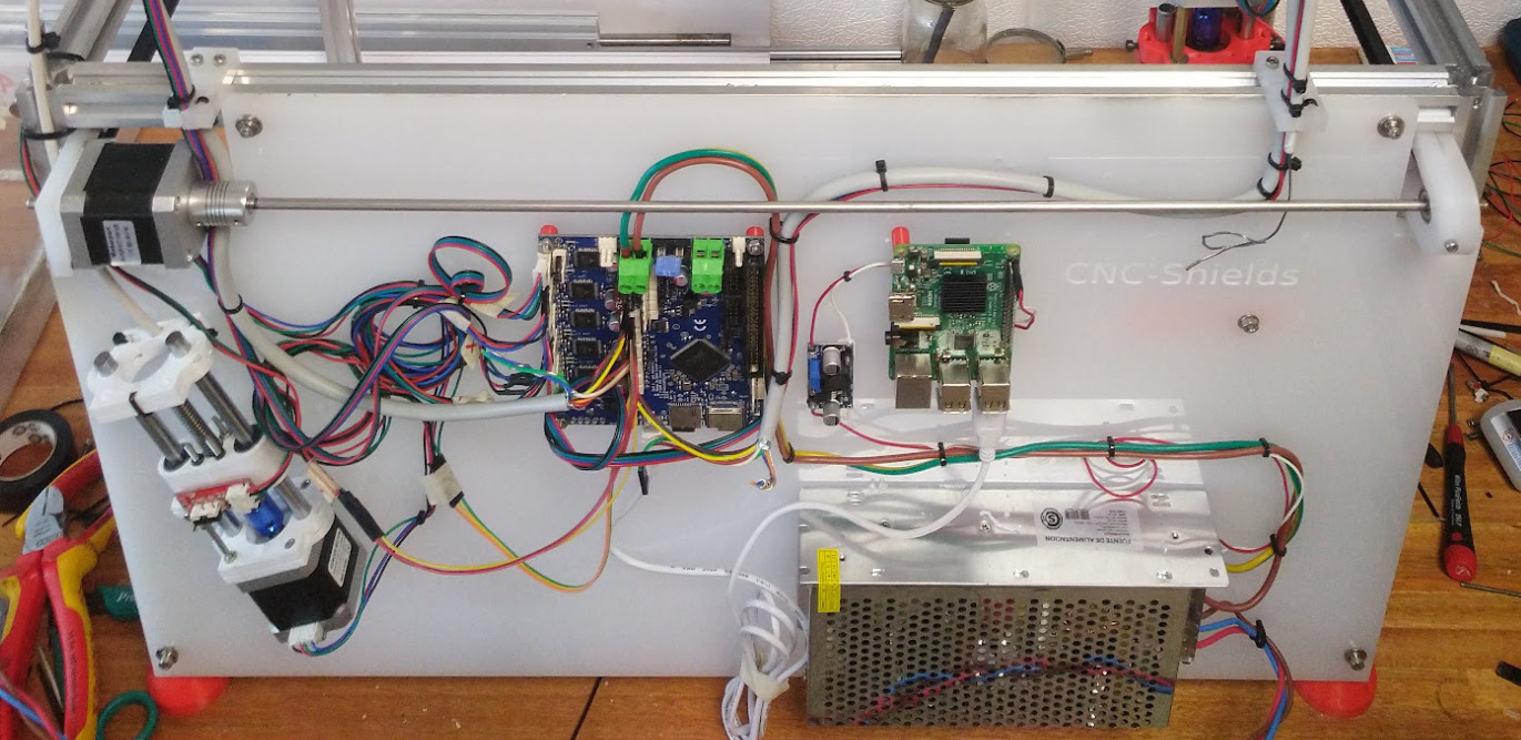
Note
The images show possible layouts for either the Duet2 WiFi, or a pair of CNC-shield V3.0 controllers. There may be additional electronics mounted on the robot's tools, axes, or baseplate.
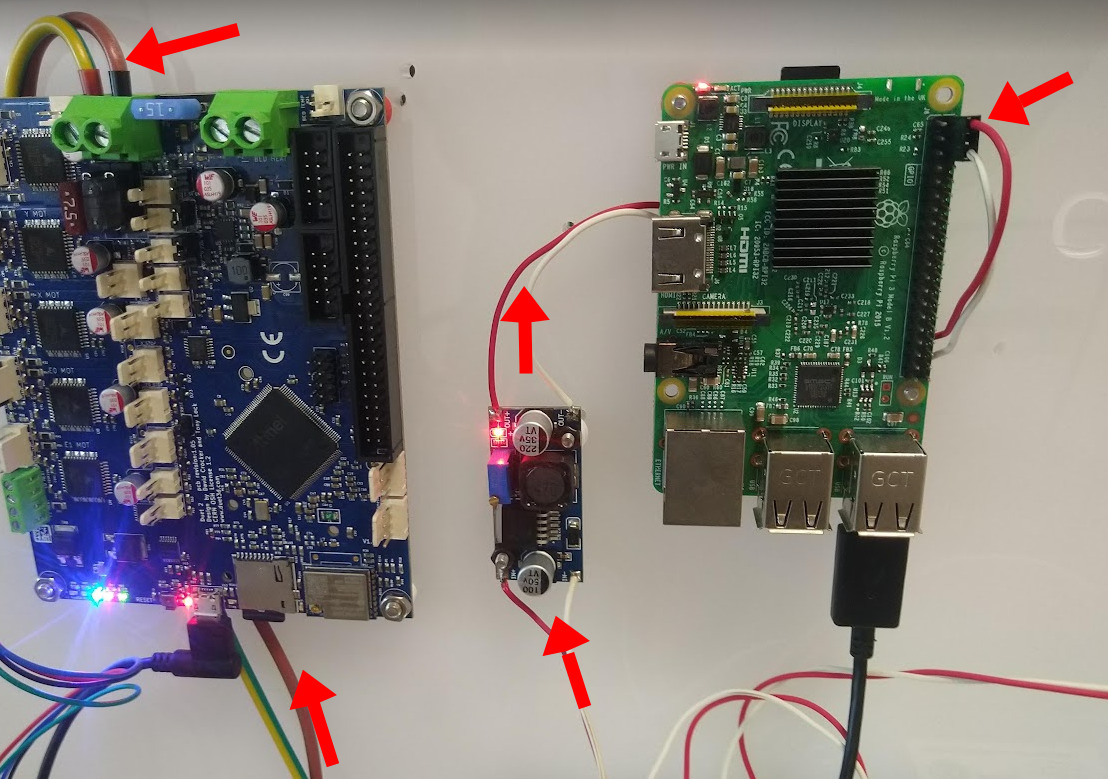
Electronics mounted on the backpanel: Arduino UNO + CNC shield operate the XYZ and Y1 axis of the CNC machine. Another Arduino UNO + CNC shield with "N+1" drivers controls the toolchanger and "N" tools. These Arduinos are controled directly from the Pi's USB ports. A step-down module powers the RPi through it's GPIO header. The main power supply can provide 10A at 24V.
Step 1: Gather parts
Parts and materials:
- 24V 10A power supply
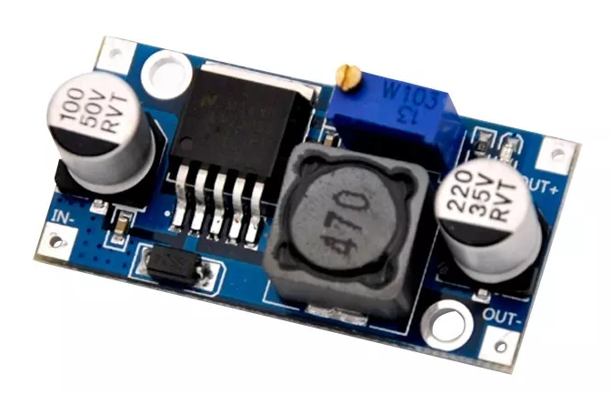
- Step-Down 24V-12V (LM2596)
- Power switch
- Cable sleeves
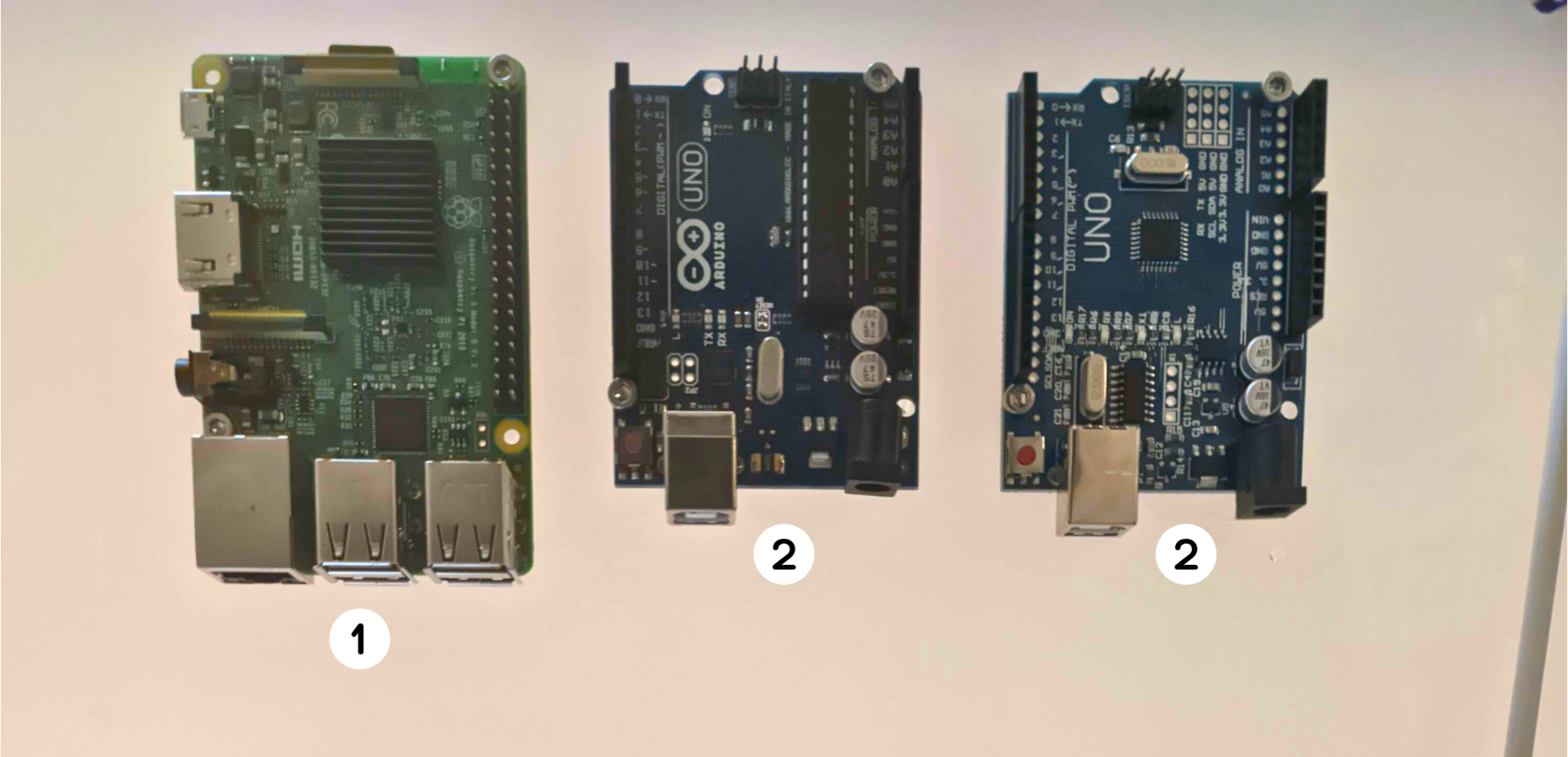
- Controllers:
- 2x CNC shield
- 2x Arduino UNO
- 6x A4988 drivers
- 1x Raspberry Pi (model 3b v1.2 or laters versions) with an micro-SD card
- Cables and wires:
- 2x USB type A-B cable
- Cables for motors and endstops
- Jumper wires
- Jumper pins
- Thicker wires for power transmission
- Female crimp pins
- DuPont connectors (1x2P 60PCS housing female for DuPont-like cable)
- 2x 30x30 cooler fans (24V)
- 5x NO mechanical end-stops
- 6 x M3 round head screws with their sliding t-nut for the endstops.
- 17 x M3 round head screws to fasten the arduinos, raspberry, power supply and stepdown.
Tools for assembly:
- Multimeter
- Diagonal cutting pliers and nose pliers
- Electronic tweezers
- Soldering iron
- Hot air rework (optional)
- Allen wrench
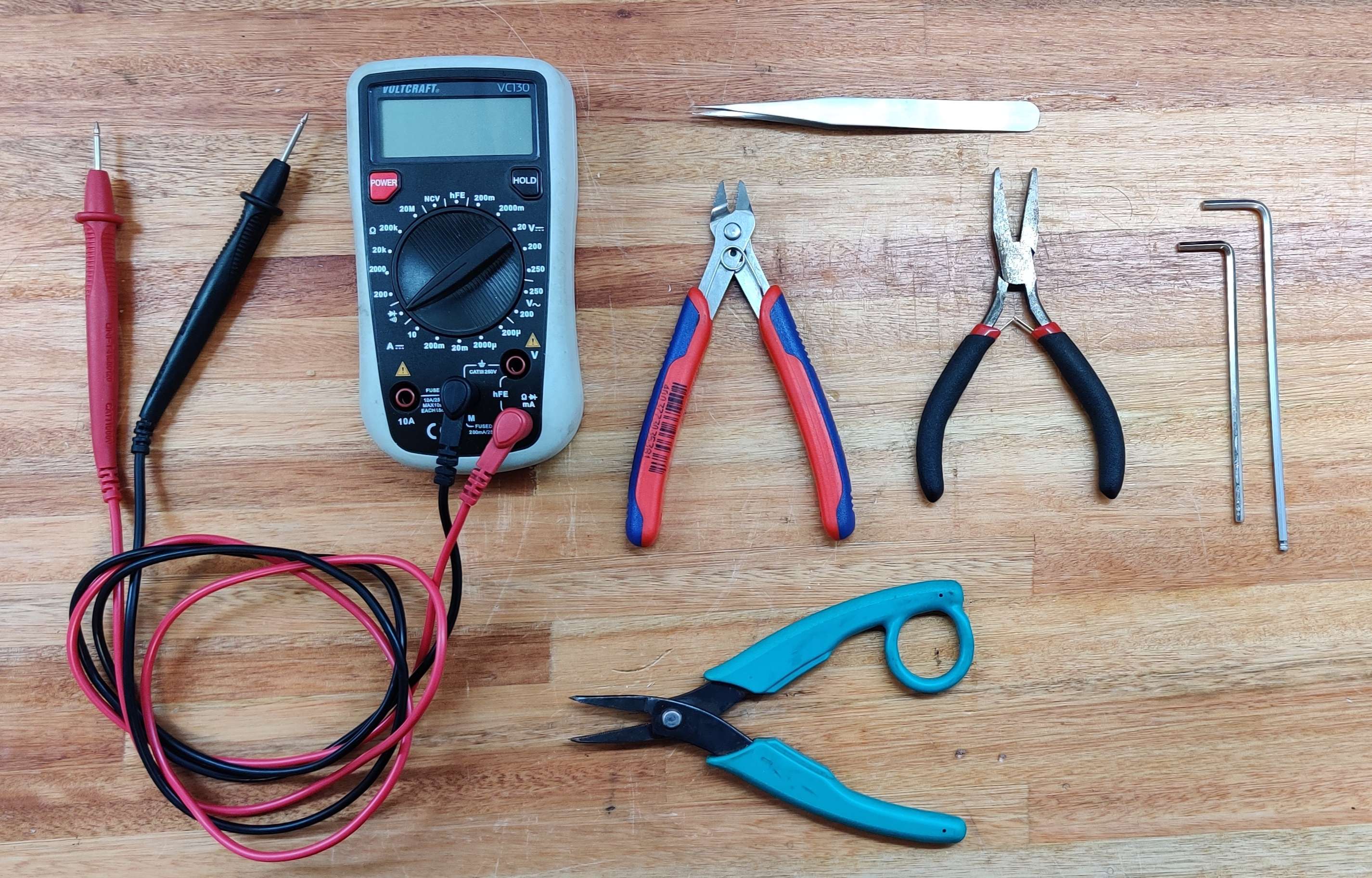
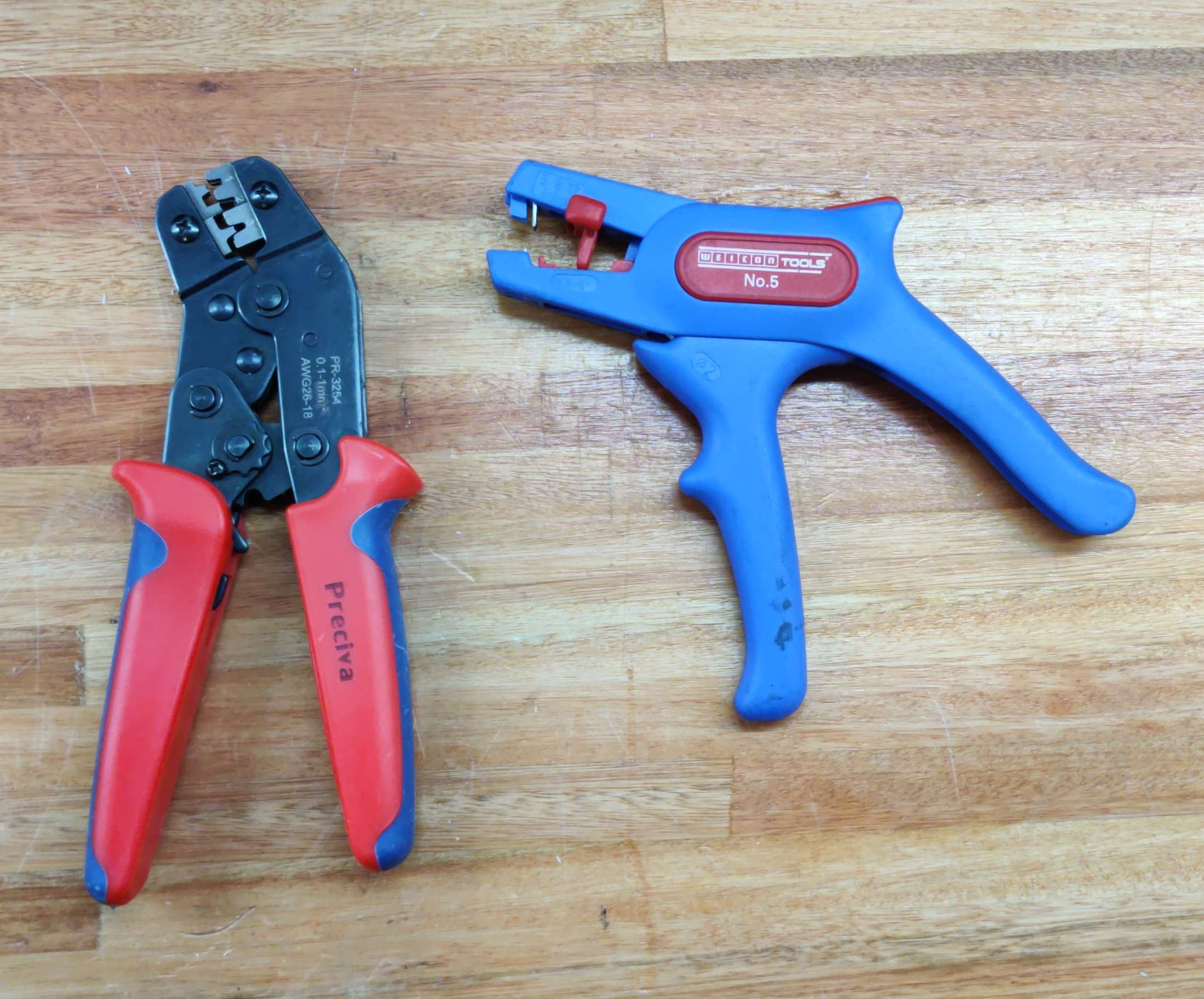
Left image: tools needed that were mentioned before. Right image: Crimping tool and Wire Stripper tool, these are optional tools that you may use if you already have them to facilitate the process.
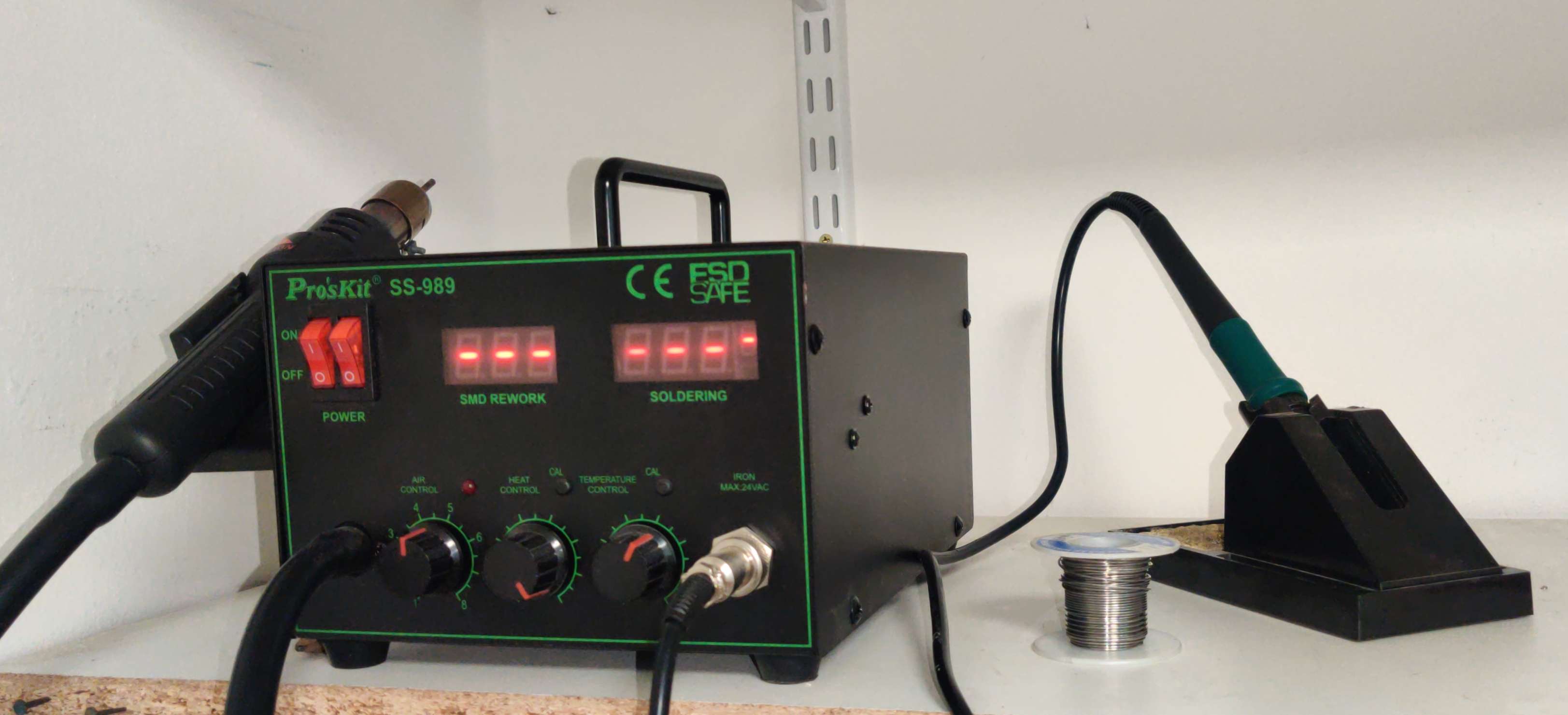
Soldering station we used (optional).
Step 2: Prepare components
Some soldering and wire cutting is involved:
Cooling fans
- Prepare the cooling fans (may need some soldering and a power connector) and solder the fan power circuit.
Power supply
- Prepare the 24V power supply with input and output connectors, and a power switch.
End-stops
- Solder endstops cables in Normal Closed configuration.
Tutorial video
How to solder wires to endstop switches and crimp dupont terminal: https://youtu.be/EWVE_HZ4YlI
Step-down converter
- Prepare the step-down converter to power the RPi (if used).
- Cut red and black wires, two pieces each.
- Solder a pair to the input side of the step-down converter, red to positive and black to negative/GND. Then connect the other ends to the 24V power supply, again follow the
red/+andblack/-convention, otherwise the LM2596 will explode. - Turn on the 24V power supply, and use a multimeter with aligator clips to measure the output of the step-down converter. Use a small flat screwdriver to adjust the output voltage to 4.85 Volts. Optionally place a mini heatsink (the ones that come with Pololus) on the LM2596 IC.
- Crimp dupont connectors to the the remaining pair of red and black wires. Solder the other ends to the output pads of the step-down converter, red to positive and black to negative, always.
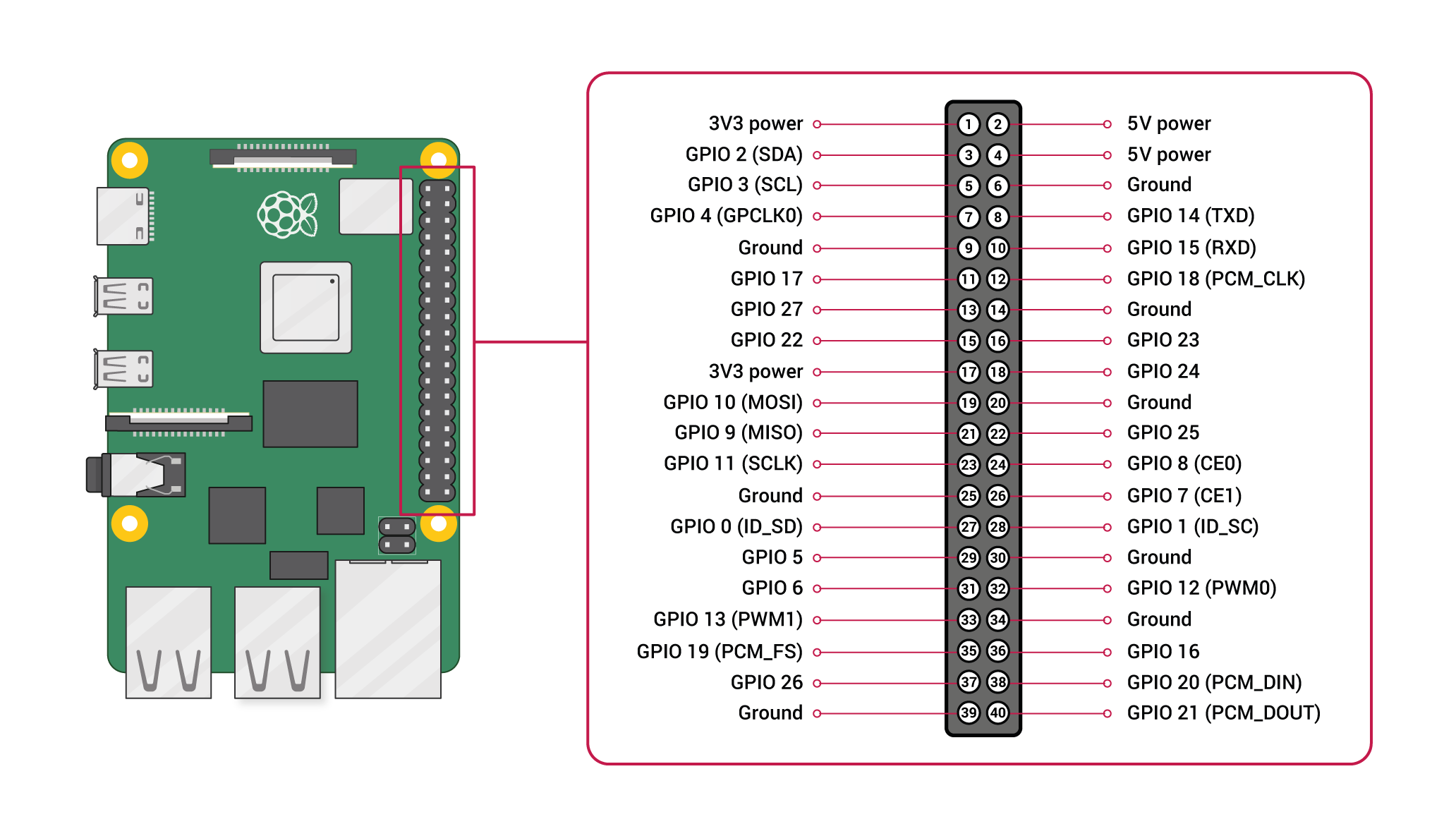
- Connect the black output wire to a GND pin of the GPIO header on the RPi (we used pin 6, see diagram below).
- Connect the red output wire to the 5V pin of the GPIO header on the RPi (we used pin 2, see diagram below).
Motor control board
Prepare the CNC control board and other microcontrollers.
- Prepare the CNC shield (jumpers, pololus, power wires, etc.).
- Add jumpers to enable the independent A-axis.
- Add jumpers to enable ⅛th microstepping on each pololu.
- Prepare the stepper drivers with their respective wires.
Cable bundles
- Cut an 8-wire cable for the XZ carriage, and crimp dupont connectors.
- Cut an 8-wire cable for the XZ tool, and crimp dupont connectors.
Step 3A: Mount motors
The motors should have been mounted as part of the assembly of the motion system.
Note
You can continue with the electronic connections without the motion system. This may even be desirable for testing the firmware configuration without the mechanics, but you will not be able to fully complete this guide.
Step 3B: Mount sensors
The motion system requires three distinct endstops for the X, Y, and Z axes, which transmit a signal when the respective stepper motor reaches the end of its path.
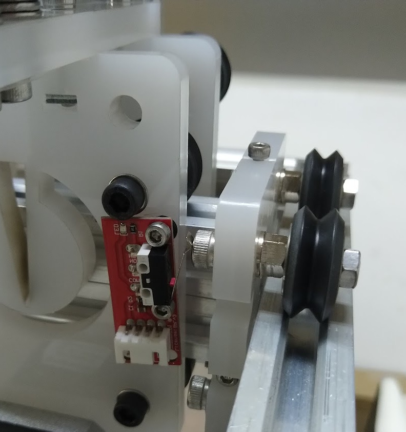
The X-axis endstop is positioned behind the X-axis carriage. Tap the mounting holes if needed, and then screw it in place (with separators in between).
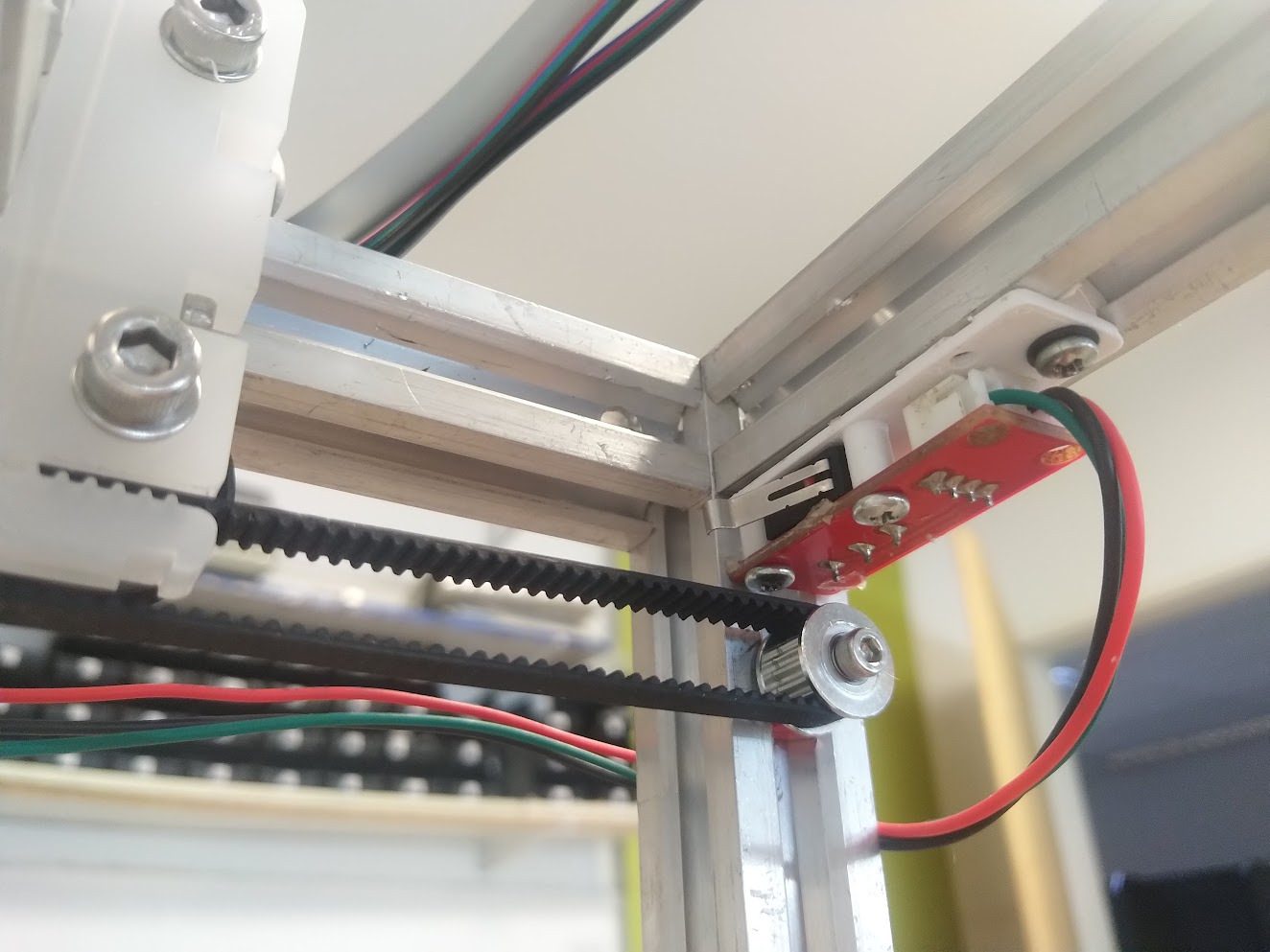
The Y-axis endstop is situated at the front-right corner, as indicated in the image below. To properly install it, you will require a sliding nut and screw.
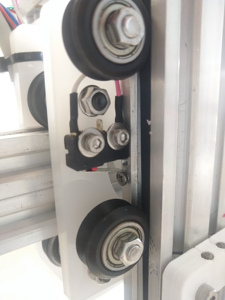
The Z-axis endstop is located on the base of the Z-axis, as shown below. Installation options include affixing it by screwing onto the part, or adhering it provisionally with hot glue.
The Z-axis endstop needs a small screw on the 2040 profile Z-axis to be triggered. It will not work otherwise.
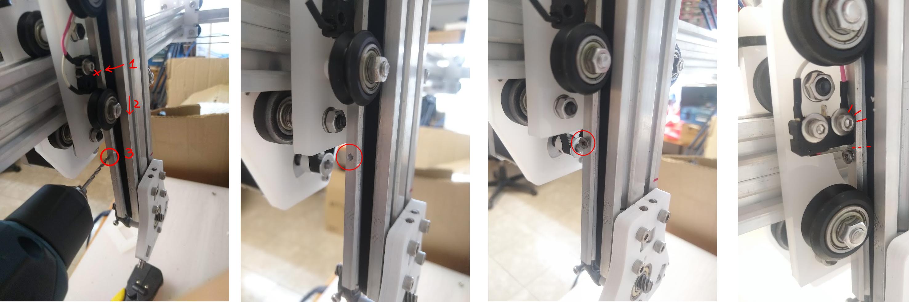
- First, turn the leadscrew to move the Z-axis to its topmost position. Then move it slightly downward (e.g. 1 mm).
- Use a small flat screwdriver to raise the endstop's lever until it clicks, and make a mark on the 2040 profile at the corresponding height. Raising the screwdriver up to the mark must be enough to trigger the endstop. The position of this mark is crucial to trigger the endstop, but also to avoid collisions between the screw that you'll be placing there.
- Lower the Z-axis until the mark is well below and clear of the carriage.
- Use a 2.4 mm (aprox.) drill bit to make a hole exactly over the mark, then tap the hole using an M3 tap.
- Insert a small cone-head M3 screw, and tighten it gently. Alternatively, use an M3 nut on the other side, and tighten it firmly, or tap a longer thread for a longer M3 screw. M2 screws would also work.
- Raise the Z-axis until the screw's head triggers the endstop, while checking that it does not collide with the V-wheels or other parts of the carriage.
Now test every endstop at least 3 times, by carefully moving the axes back and forth, checking that the endstops trigger as they should (i.e. at the ends).
Step 3C: Connections and cable management
TODO
A guide is due. It must cover the bases for cable bundles too.
- Select and trim cables ensuring they meet the necessary length and wire-count requirements.
- Organize and bundle cables, allowing the robot to move freely.
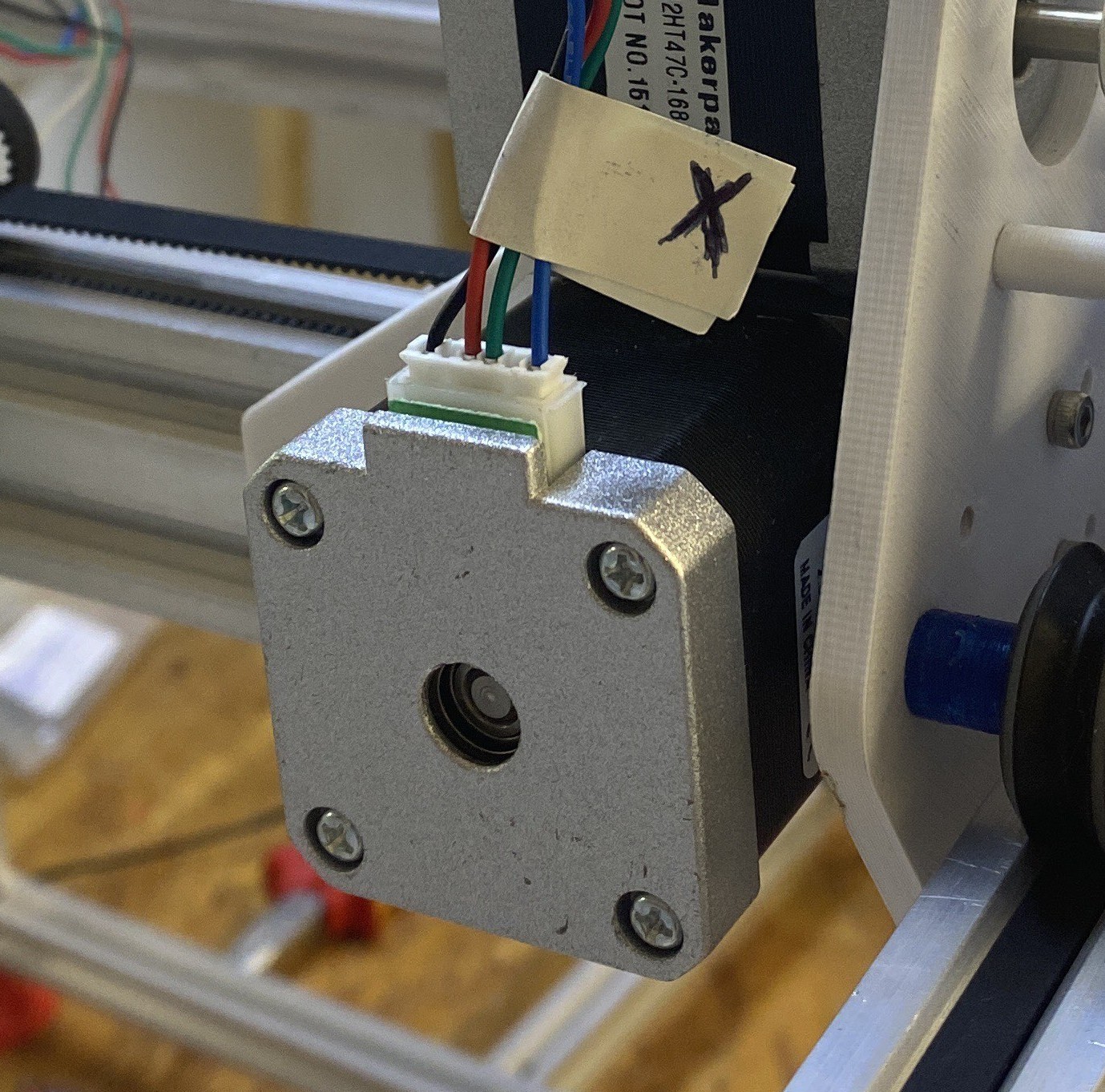
- Label both ends of each cable when connecting it. This will be crucial later on.
Tip
Always label your cables. The situation will become confusing really fast.
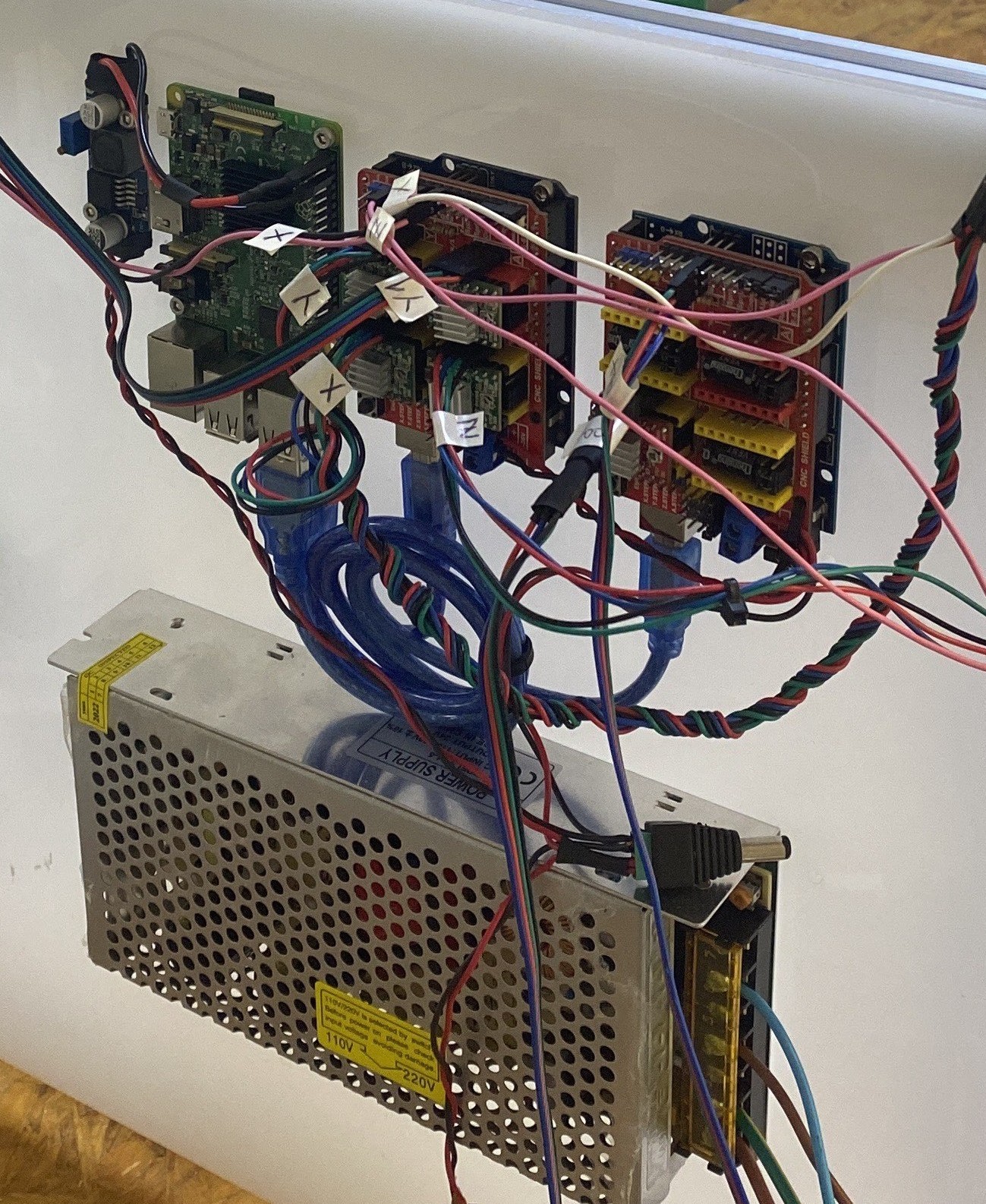
Tip
The electronics will be organized as shown in the images. Take this into account when laying out and managing your cables.
Step 4: Mounting the electronics
Once you've made the backpanel, you're ready to mount the electronics.
Tip
Before mounting the Raspberry Pi and CNC control boards, it's convenient to install software and firmware on them. You can do this later on with only minor discomfort.
- Instructions for the RPi.
- Instructions for the CNC boards.
Important
Always place a 3D-printed 5 mm separator column on the screws, between each component and backpanel.
Tip
The acrylic backpanel may have engravings suggesting where to place each component.
Use M3 screws and separators to attach the following components to the backpanel:
- Raspberry Pi on the left side of the backpanel. The Pi's PCB barely fits the M3 screws, do this very gently.
- Two Arduino UNO boards (if applicable) to the top-right of the backpanel.
- Duet boards (if applicable) to the center-left side of the backpanel.
- 24V PSU to the bottom-left side of the backpanel.
- The step-down converter.
Step 5: Connect cables to the electronics
- Make all connections.
- Keep track of the connections, this will be essential to completing the CNC configuration steps of the Electronics setup guide
Warning
Always disable the power supply before connecting and disconnecting steppers and Pololus to the CNC Shield. You will risk damaging the Pololus if you do not cut the power before.
Duet2 WiFi
Warning
A guide is due.
Arduino CNC Shield
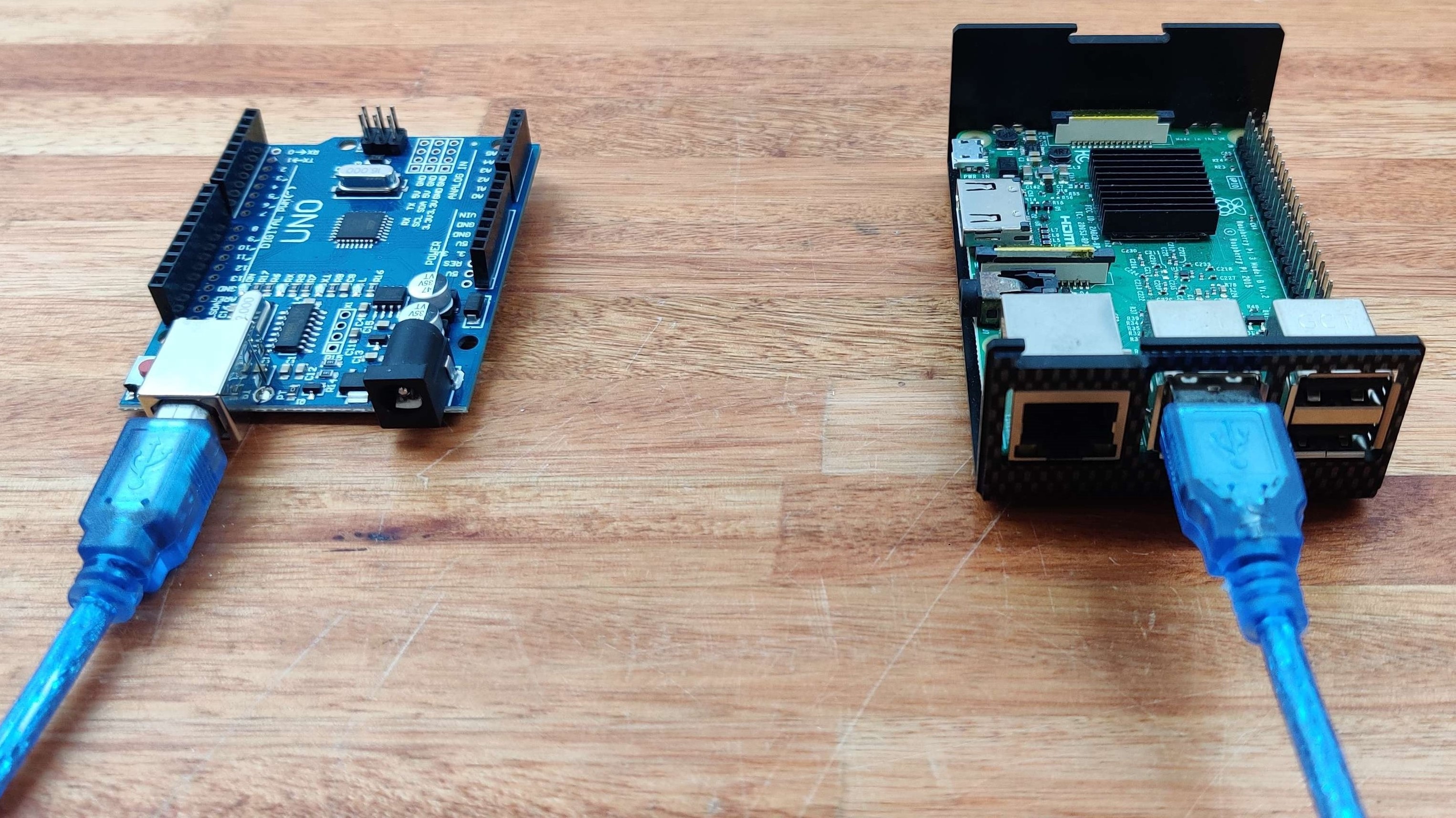
- Connect the Raspberry Pi's (or PC's) USB port to the CNC's USB port.
You'll need the USB type A-B cables for the Arduino UNO, and a USB-A to micro USB cable for the Duet2 WiFi.
Add two jumper pins to each stepper driver slot on the CNC shield, as shown on the image below. This will set ⅛th microstepping on each driver.
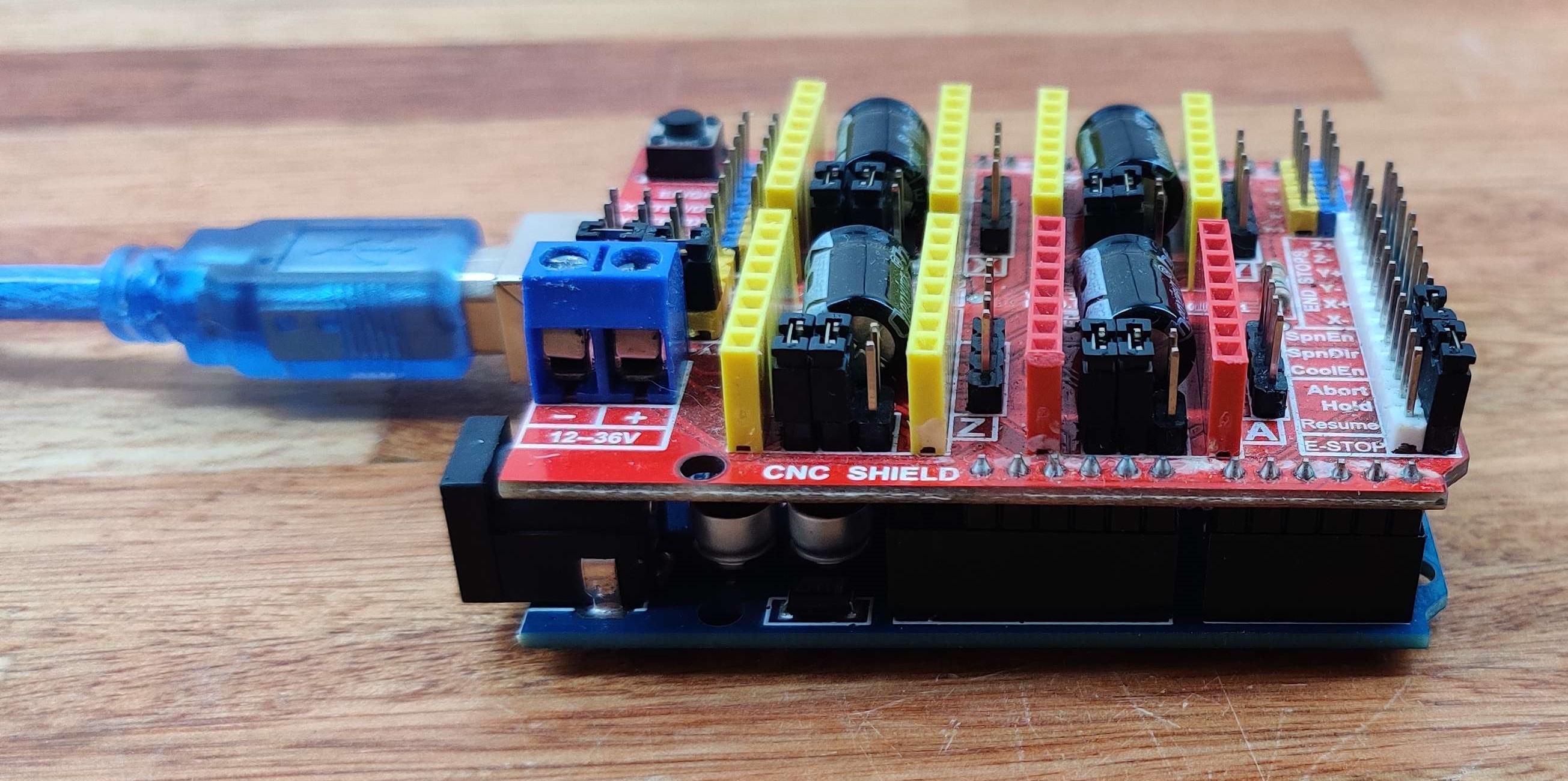
Fit the CNC shield on the Arduino and put the stepper motor drivers matching, their enable pins with the EN pins on the CNC shield. The drivers capacitor goes to the reset side of the cnc shield.
Danger
The drivers will be destroyed if you connect them in the wrong orientation.
Then, place two jumpers as shown the picture below. This will enable the A-axis slot, which we use to drive the second Y-axis stepper.

Alternatively, if you put the jumpers in the Y headers, the motors of the Y and A slots will share the direction and distance pins. Because the Y-axis motors are one in front of the other, they will need to rotate in opposite directions to move the two Y-axis carriages in the same direction. This also means that you'll only need to configure one Y-axis stepper in Klipper.
In this case, to invert the direction of rotation of one of these steppers, you can flip the stepper's connector on the CNC shield. This procedure can be used to flip the direction of rotation of any stepper, without using software settings.
This is how it should look on the backpanel so far:
Afterwards, connect the (X, Y1, Z, Y2) motors in (X, Y, Z, A) headers and the (X, Y, Z) end-stops of the CNC shield respectively, as the following image shows.
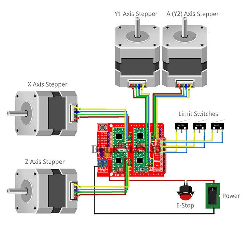
Arduino UNO pin map (click to open/download). It shows the pin names of the ATMega328p microcontroller (used by Klipper), and their common names on the Arduino UNO board and the CNC-Shield (V3.0 clone).

Using the pin map above as reference, the pins for each connection on the CNC shield should be:
- X axis stepper: PD2 - PD5
- Y axis stepper: PD3 - PD6
- Z axis stepper: PD4 - PD7
- A axis stepper: PB4 - PB5
- This is the Y1 stepper, or second motor for the Y axis.
- Remember to add jumper pins to allow this Pololu to move independently.
- X endstop: PB1
- Y endstop: PB2
- Z endstop: PB3
Info
To connect the second Arduino UNO + CNC shield with "N+1" drivers controls the toolchanger and "N" tools, you should repeat the same process adding the toolchanger driver to the X header and the tools drivers in the (Y, Z, A) headers. Remember to put the jumpers in the same place as the other Arduino UNO.
Tool connections
Connect all tools to the control electronics.
- Pipettes
- Other stuff!
The robot currently features two extrusion motors controlled by the second Arduino. The first one should be connected to the X slot, controlled through the T0 G-code macro command. Meanwhile, the second extruder should be connected to slot A on the same Arduino, and activating its control requires the T1 G-code macro command.
The way to connect any tool is the same as connecting the motors.
Step 6: Power connections
Power the PSU
Disclaimer
Excercise EXTREME CAUTION when connecting the power supply to 220V AC mains power. Ensure that all the connections are made safely, securely, and correctly, while adhering to proper safety measures to prevent any accidents.
Mains power is dangerous. These instructions are provided with no guarantees and, while reviewed, may contain minor errors in their content. Follow them only at your own risk, or ask a professional to do it for you. The responsibility for your safety and prevention of equipment damage is yours only.
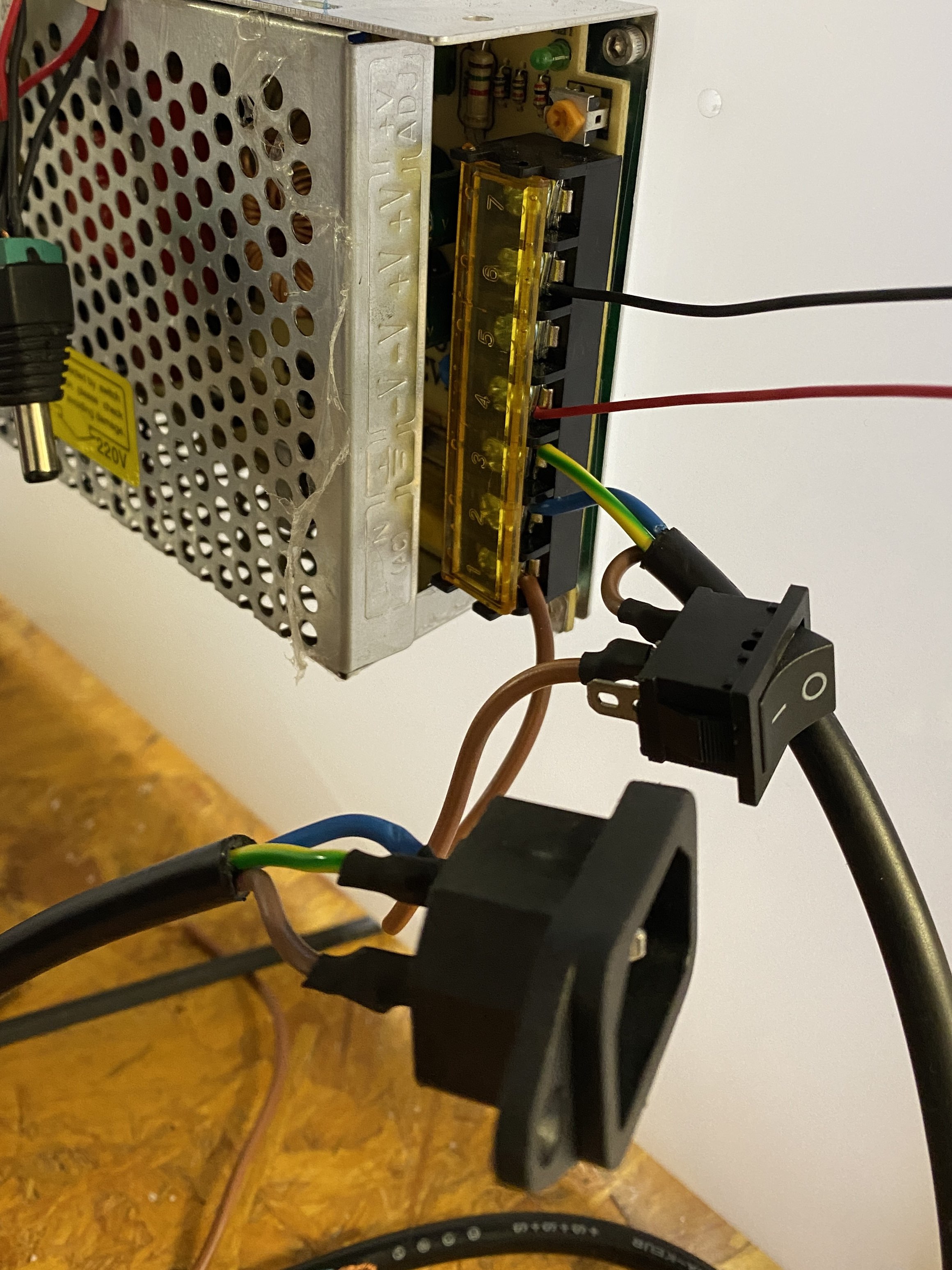
- Check that the PSU is set to the correct AC voltage (e.g. 110V for the US, 220V for Argentina, etc.).
- Connect the PSU's Live, Neutral, and Ground terminals to the corresponding pins of an IEC female connector (IEC 60320-1), with an appropriate power switch in between.
- Make sure that the connections are robust and insulated (e.g. with heatshrink).
- Secure the IEC connector and power switch to the backpanel.
- Connect a multimeter to the ± output terminals of the PSU. Make sure that they are connected securely, won't move, and won't touch any other terminals.
- Disconnect any other wires from the PSU.
- Make sure that the switch is in the OFF position with a multimeter.
- Triple check all connections, the following steps involve mains power.
- Connect the female IEC connector to mains power through a power cord with a male IEC terminal.
- Turn on the PSU by flicking the switch. A small indicator LED might light up on the PSU.
- The multimeter should display some number close to 24V DC. 1 Find a small screwdriver and very carefully turn the potentiometer to adjust the voltage to around 23.0V-23.5V (or well below the maximum rating of the stepper drivers and driver boards).
- DO NOT touch anything else with the screwdriver. If this seems difficult, remove power from the PSU before making the adjustment, and re-connect after making the adjustment to read the current voltage.
- Power off the PSU.
Power the Electronics
Warning
Be careful with polarity!
- Wire the cooler fans to the PSU (if applicable).
- Wire the input side of the step-down converter to the PSU. Turn the PSU on and adjust its voltage to 4.95V (never more than 5V).
- Turn off the PSU.
- Wire the output side of the step-down converter to the Pi's to its GPIO header. You will fry it if you mess this up.
- Wire the input of the CNC control boards to the PSU.
Info
The power supply provides 24V to the CNC shield and to a step down converter (24 to 4.85V), which in turn powers the Raspberry Pi with 5V using pins 2 (5V) and 6 (GND).
Interactions
The electronic section of the pippetin interacts directly with the backpanel from which it is attached, but more importantly it interacts with all stepper motors, endstops, pipettes and tools. As indicated in the assembly section, they are connected to all the parts through cables to control and regulate the operation.
Maintenance
In all cases, disconnect power before doing any maintenance on the electronics.
Dust will accumulate on the electronics, which may cause issues if unattended. Check for accumulation of dust and signs of corrosion regularly.
It may also be a good idea to snif around the electronics too, looking for any strange smell coming out of it.
If a particular stepper seems to be malfunctioning, try replacing the stepper driver.
Design
The electronic components were not designed by us, but we chose them according to their openness and ubiquity.
For example, the Raspberry Pi, Arduino UNO, CNC-Shield v3.0, and Duet boards are all open source hardware designs.
Most of these are also ubiquitous, except for the RPi and the Duet, which are easily replaced by a Linux PC and Arduinos, respectively.
Models
The only models used for the electronics are those corresponding to the "backpanel" in charge of supporting the electronics. You can find them by clicking here
Software
Find everything you need to know about pipettin software at Software Setup Guide
Development
The Backpanel was designed in FreeCAD 2.1 and 2.0, then cutted in a laser CNC (cutting program: LightBurn Beta 0.8.07).
To learn more about these file formats visit here.
Congrats!
By completing these steps you have wired and cable-managed the electronics of the robot.
You may return to the assembly guide to continue: Assembly Guide