Tip Ejection Post
Introduction
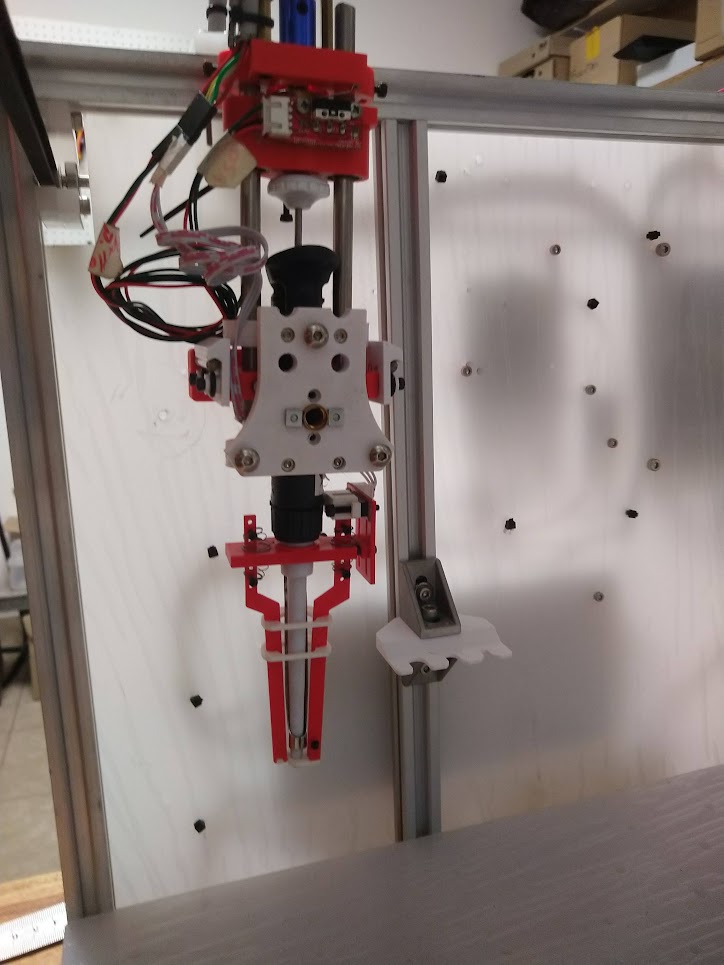
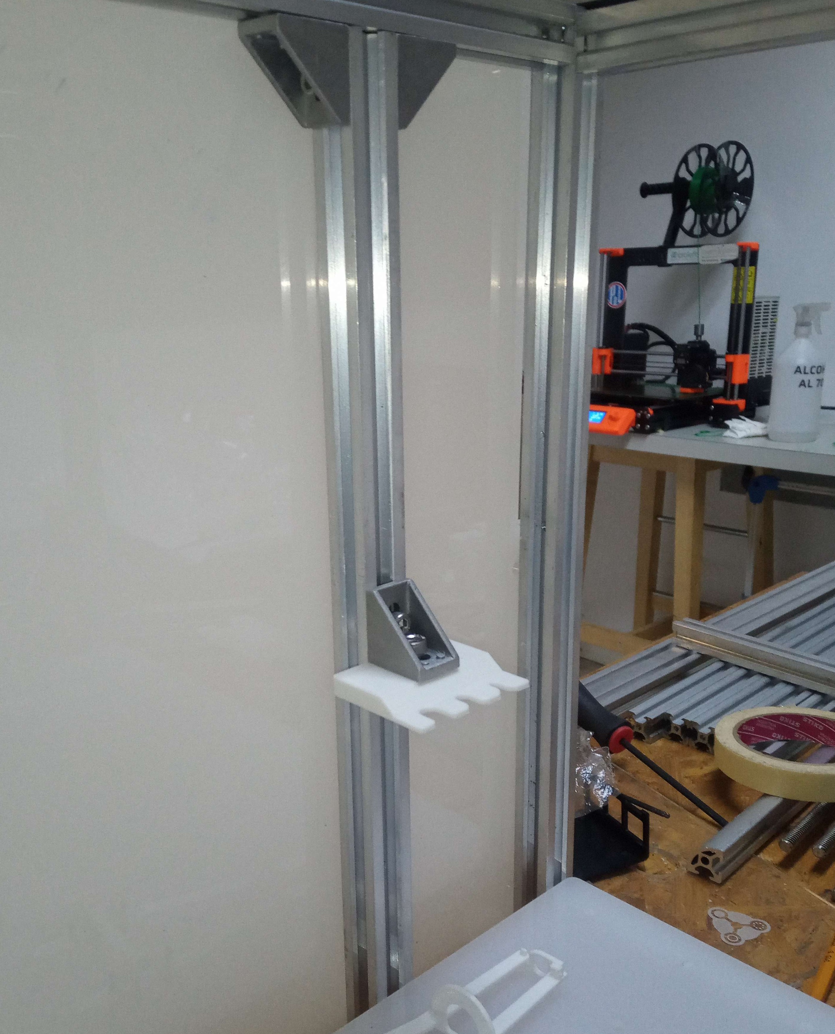
This page describes the "tip ejection post", a passive structure fixed to the structura frame, that a pipette tool can use to eject its tips (if it does not have a tip ejector built-in).
Info
Related issues:
- https://gitlab.com/pipettin-bot/pipettin-bot/-/issues/118
- https://gitlab.com/pipettin-bot/pipettin-bot/-/issues/80
- https://gitlab.com/pipettin-bot/pipettin-bot/-/issues/140
Communication channel: https://discord.com/channels/1042462799772782613/1166140074157686804
Overview
Overview documentation:
- Type: Project documentation.
- Audience: General community.
- Content: Definition of the project or general objective. Explanation of what you did, what it is for. General overview.
The objective is to enable micropipettes without tip ejectors to discard (i.e. eject) tips to a "trash bin", by means of a fixed "post".
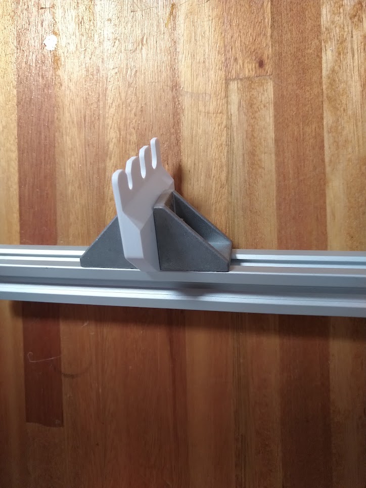
On it's lowermost end, the post has fork-like structures, one for each tip size, that the pipette can use to remove tips from it's tip holder, by docking with it and moving upwards.
Usage
Usage instructions:
- Type: Technical documentation.
- Audience: Users.
- Content: Instructions for intended use, alternative usage modalities, usage restrictions (related to design choices, functional specification, and elementary operating principles).
- Troubleshooting: Clarify if there might be any problem with the use of what you did and how can you adapt if you have a problem.
- Precautions: Indicate if there are any precautions that must be taken.
The post is used by the robot to eject tips when requested. Beneath the ejector there must always be a trash bin, which the ejected tips can fall into.
The bin should be made of a corrosion-resistant material, be emptied and cleaned regularly.
Each new tool that requires the post must be calibrated beforehand (see installation below).
Caveats and Limitations
- Document type: Technical documentation.
- Audience: General community.
- Content: Current issues, potential problems the audience might encounter, and limitations of the work (both temporary or long-term). Enumeration and explanation of the most important problems, bugs, limitations, and other issues of this work. Instructions for how to avoid or patch them, proposals for possible fixes, links to GitLab issues, etc. It is prioritary that all "caveats" are documented, as this will help users understand the limitations of the work, and be offered to contributors as possible objectives.
Assembly
Assembly and manufacturing:
- Document type: Technical documentation.
- Required resources: parts, tools, environment, and skills required to build the project.
- Audience: Makers, Users.
- Content: Bill of Materials (materials and parts). Full description of assembly steps, parts, required knowledge, skills, time, and tools. Manufacturing instructions for custom parts, shopping list for comercially available parts and possible suppliers.
- Precautions: Indicate if there are any precautions that must be taken.
Note
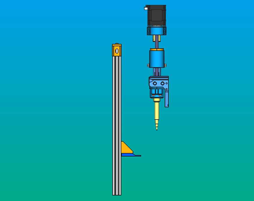
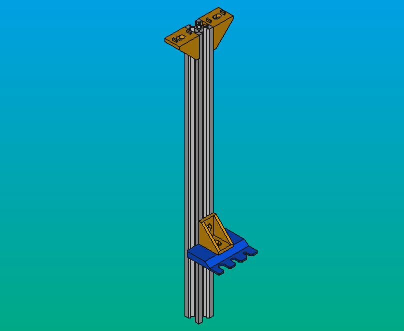
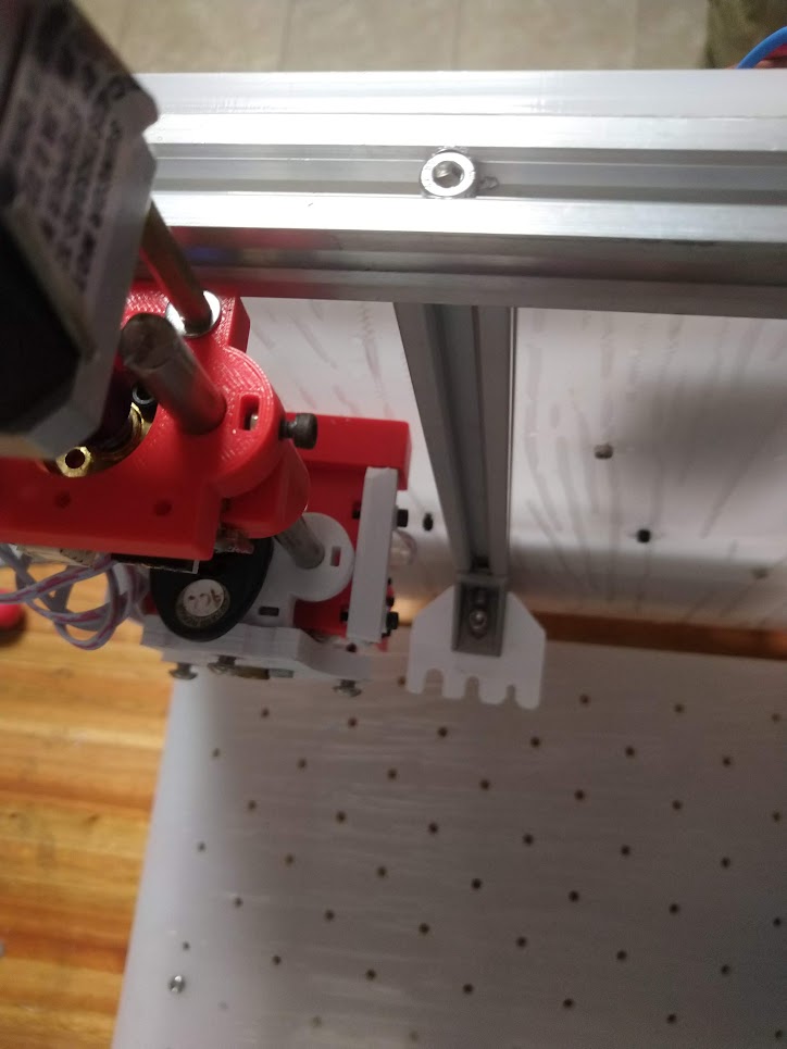
The objective is to place the tip ejector in a convenient location, such that that the pipette tips can be easily removed, as shown in the image below.
Gather parts and tools
Required parts:
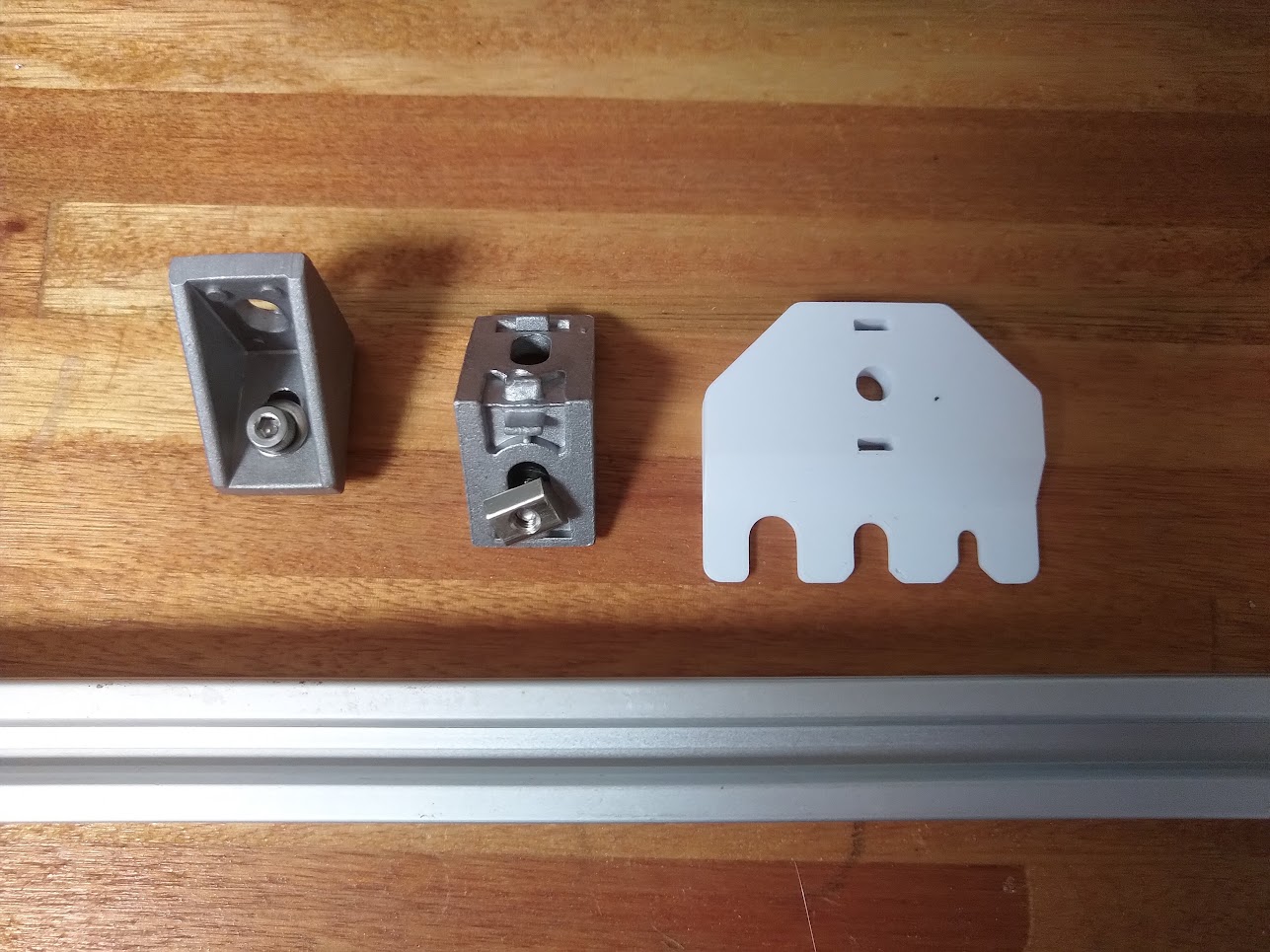
- Tip ejector pads:
PIP-TIPS-EJECTOR(3D-printed).
Required materials:
- Screwdriver.
- Drill.
- 6 mm drill bit.
- 500 mm of 2020 V-slot aluminium extrusion.
- M5 thread tap.
- 25 mm M5 screw.
- 20 mm M5 screw.
- M5 nuts and washers.
- M5 slider nuts for 2020 aluminium extrusions.
- Corner bracket for 2020 aluminium extrusions.
- Optional:
- 4.5 mm drill bit (or similar) for aluminium.
- Aluminum 20 x 20 V profiles.
- PLA filament: 300 g
Required tools:
- Aluminium cutting tool (bandsaw, miter saw, regular saw, angle grinder).
- 3D-printer.
- Manual drill
- M5 and M3 screw tap
- Band-Saw
- Band: 20 x 2362 x 8/12d
- File
- Drill Press
- Cooling lubricant
- 3D printer
Required skills:
- General workshop skills (e.g. using a vise, a saw, tapping threads, etc.).
Prepare parts
Warning
A guide is due.
- 3D-print the ejector pads.
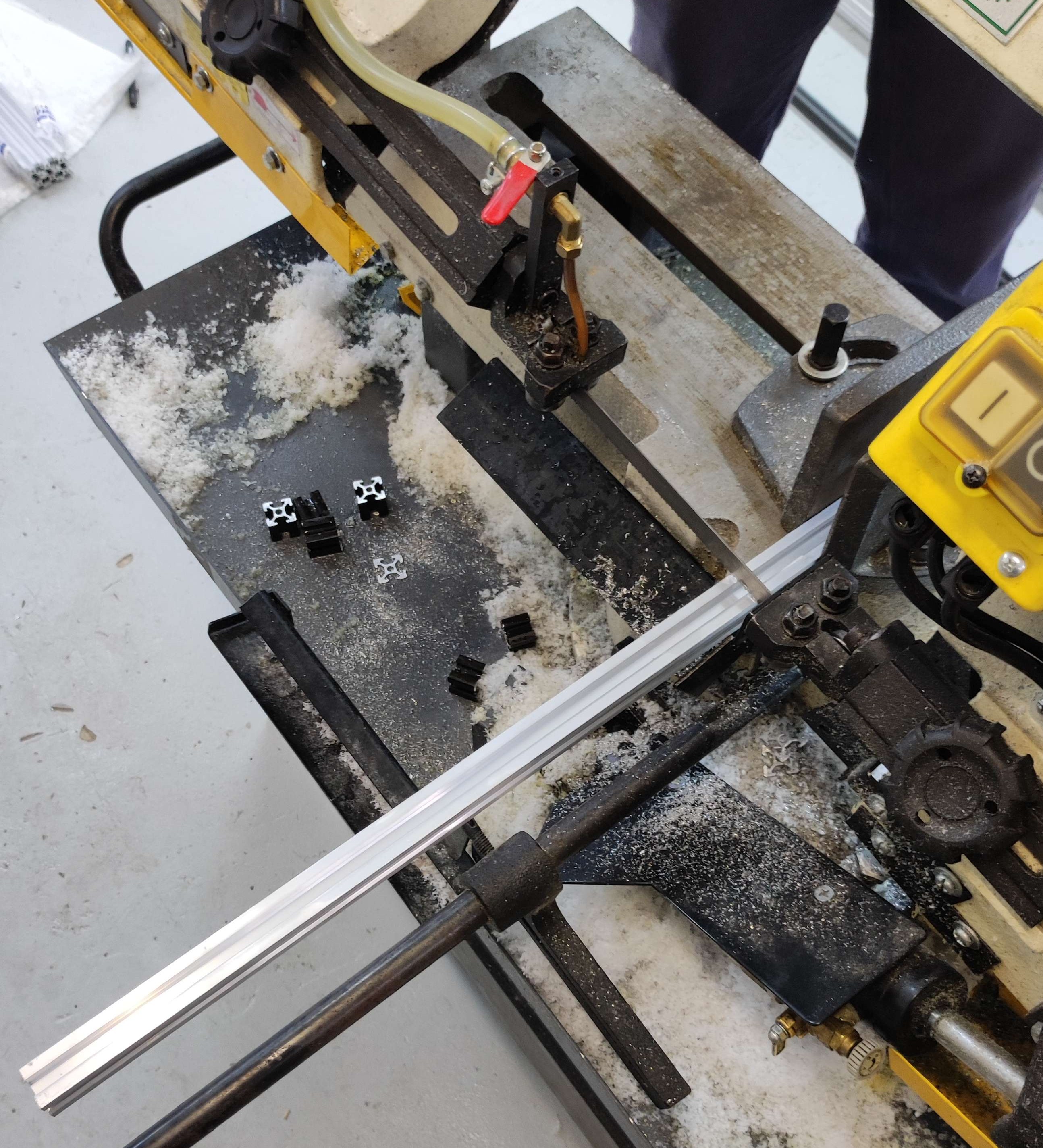
- Once you have all the parts, you need to measure the dimensions of the structure and the baseplate, specially the distance between the lower part of the top profiles to the surface of the baceplate, to cut the 20x40 V profile with the Band-Saw.
- Cut the profile to an appropriate length (i.e. measure the distance from the underside of the top profiles of the structural frame, up to the underside of the baseplate).
Tip
This height will be, at most, from the upper surface of the baseplate to the lower surface of the top 20x20 V-profiles of the structural frame.
This measurement can be fully determined once you have assembled the structure. Likewise, any movement can be corrected through programming. It is better to have a larger profile than a shorter one.
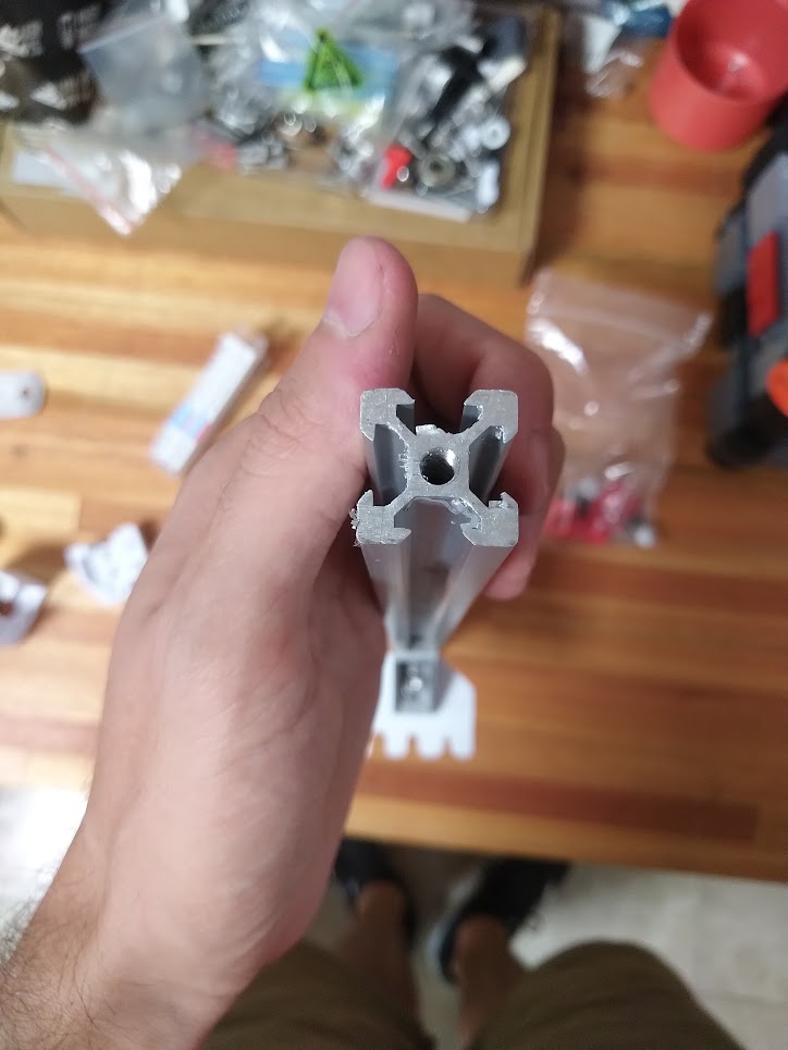
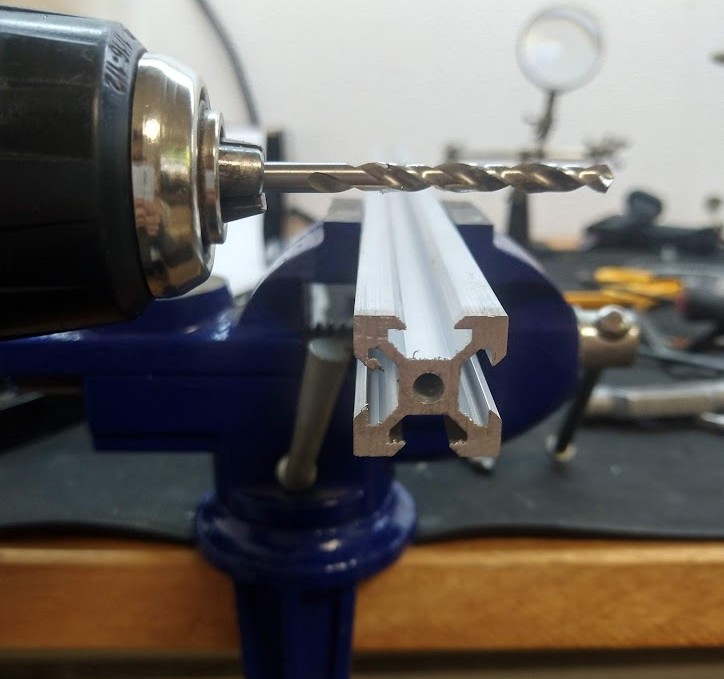
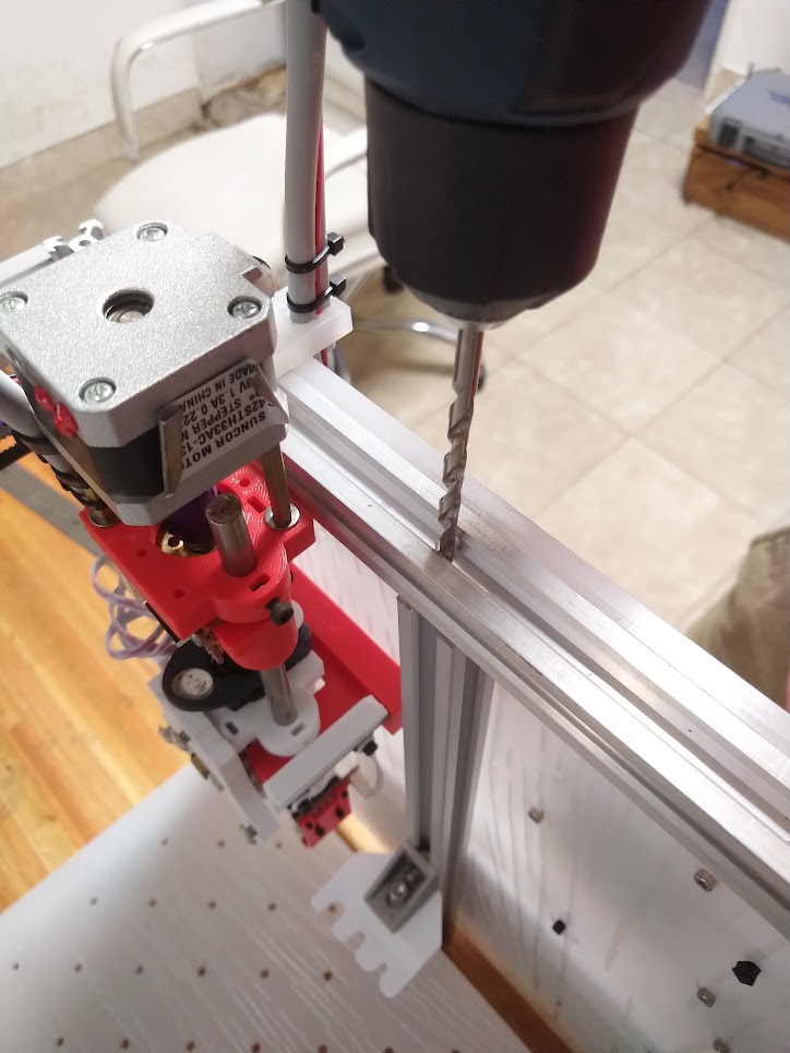
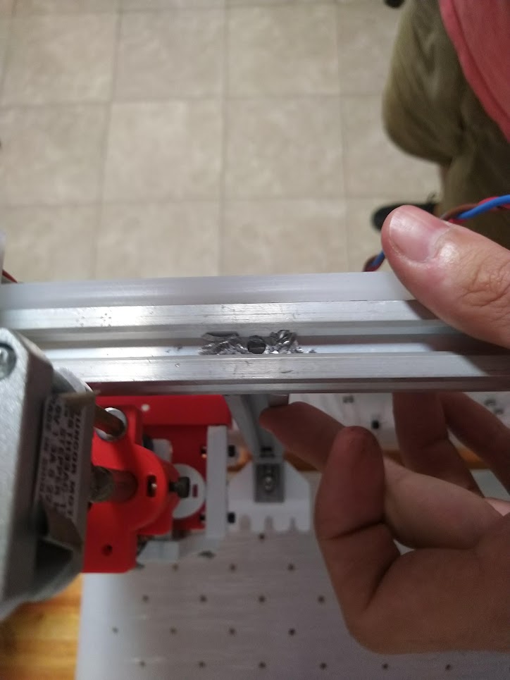
- If you choose to attach the post to the frame without corners, use an M5 tap to thread the center of the profile.
Tip
Try passing a 4.5 mm drill bit through the profile before tapping. It will be much easier, and reduces the risk of breaking your tap.
Mount the ejector pad
Insructions to attach the ejector pad to the post's aluminium profile.
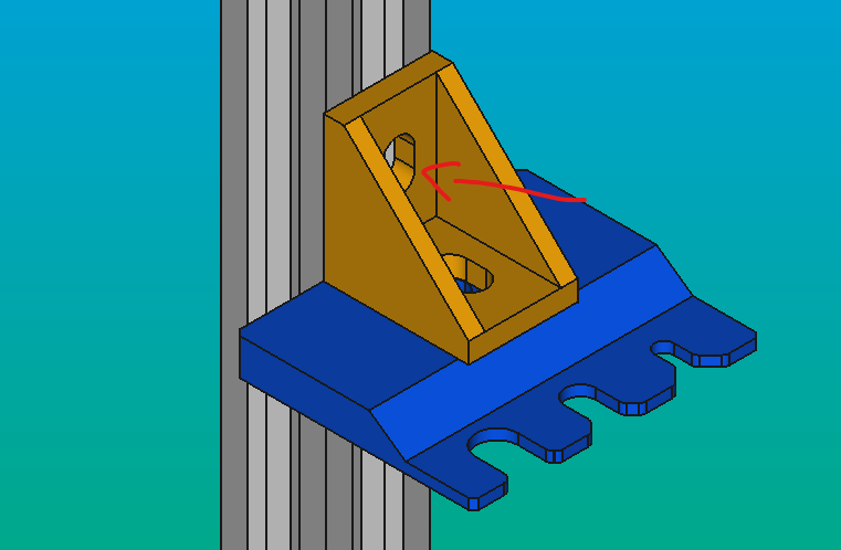
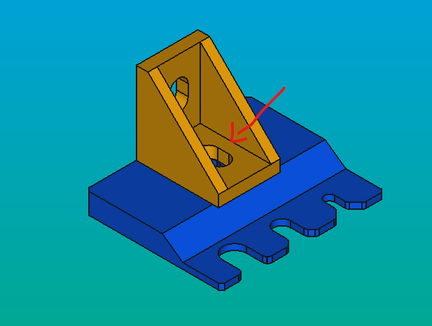
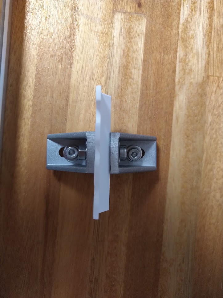
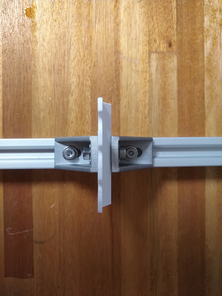
- Attach one corner square to the 2020 profile with a M4 screw, and a profile nut (red arrow).
- Align the PIP-TIPS-EJECTOR piece (blue) to the corner square (orange) with an M4 screw.
- Optionally:
- Attach a second corner to the profile, below the first one, but do not tighten its screw yet.
-
Sandwich the ejector pad between the corner squares, sliding the lower one upwards.
-
Tighten the pad to the corners by adding an M4 nut. If you added a second corner below, tigten its screw now.
Mount the profile to the structure
Insructions to attach the post's aluminium profile to the machine's frame.
There are two options for this step.
With corner squares
- Attach two corner square at the perpendicular sides at the top of the profile
- Attatch the corner squares to the bellow part of a horizontal 2020 profile of the structural frame
With a tapped post
- Align the ejector post. Find a cozy place for it.
- Make a mark on the top profile, aligned to the post's center below.
- Set the ejector post aside, and drill a 6 mm hole through the frame's profile.
- Re-align the post, insert an M5 screw through the hole, and tighten firmly. the post should not flex at all.
Alignment
You may need to adjust the height of the ejector pad in the future.
Do this by slightly loosening the screws that fix the corner squares to the profile, and moving it upwards or downwards, as required.
Installation
Hardware and software installation instructions:
- Document type: Technical documentation.
- Tools and skills: tools required to install, setup, or callibrate the hardware and or software.
- Audience: Technical support, Makers, Users.
- Content: Complete description of installation steps and required knowledge, environment, number of people, skills, time, and tools. Links to learning resources. This applies to installation of software (e.g. OS, compilation, dependencies, drivers, etc.) and hardware (e.g. location requirements, operating conditions, etc.).
Once installed, the post's coordinates must be calibrated.
- Adjust the height of the ejector pads, such that all tools that use it. Then fix it in place tightly.
- Calibrate the tip-ejection coordinates for each tool.
- Test the ejection procedure.
Warning
A calibration guide is due.
Interactions
Interfaces and interactions:
- Document type: Technical documentation.
- Audience: Makers, Users.
- Content: Indicate how it connects to other parts of the robot, and all parameters relevant to those interactions and/or interfaces. Also comment in which section of the documentation you think your material goes (Assembly, Maintenance, Design, Development, etc.).
The ejector post interacts with:
- The structural frame, on which the ejector is mounted.
- The tip holder part of micropipettes.
Maintenance
Maintenance procedures:
- Document type: Technical documentation.
- Audience: Technical support, Users.
- Content: Required maintenance operations, frequency, tested replacement parts and compatible alternatives.
- Precautions: Indicate if there are any precautions that must be taken.
Inspect the ejector pads for damage or wear.
To replace the ejector pads:
- Print the new pad.
- Remove the top square bracket to release the old pad, but not the bottom bracket.
- Install the new bracket, reattach the top bracket, and tighten firmly.
- Check that your tools can still eject tips correctly.
Tip
If done carefully, you should not need to re-calibrate.
This part should not require any additional maintenance.
Design
Design principles:
- Document type: Technical documentation.
- Audience: Developers, Contributors, Educators.
- Content: Description of the overall design rationale. List of the main design choices and implications (e.g. functional compromises). Minimal explanation of the working principles. Specifications of the internal and external hardware or software interfaces. List of standards that apply.
Models
Hardware design files:
- Document type: Source files.
- Audience: Developers, Contributors.
- Content: Design files with parts metadata, typically including: mechanical models (e.g. FreeCAD), schematics for electronics (e.g. KiCAD), technical drawings, specifications of parts and materials, etc. Distinguish between custom parts (e.g. developed as a result of this or another project), off-the-shelf parts (e.g. screws), or complex modules (e.g. a single board computer). Specification for all hardware interfaces.
- Explanation of the part-naming scheme/convention.
Software
Software and firmware sources:
- Document type: Source files.
- Audience: Developers, Contributors.
- Content: Original computer code for the programs required to operate the machine to its full capability. Detailed instructions to build and/or install the software and its dependencies and their specific versions. Specification for the programming interfaces (APIs) if any.
Development
- Document type: Technical documentation
- Audience: Developers
- Content: Development flow and tools (e.g. IDEs, EDA, or CAD software), file formats, and guidelines used to develop the project. Description of setups for development and testing. Detailed description of the hardware modules and software, and corresponding source files. Tutorials and examples for how to get started or adding new modules.
