Micropipette Adapter Tool
Introduction
This page describes the "gilson micropipette adapter", an active liquid handling tool fitting a single tip type.
It has a built-in actuator for its tip ejector, and a "tip placement sensor" that can tell when a tip is placed to the correct depth.
Info
Related issues:
- https://gitlab.com/open-la/pipettin-bot/-/issues/223
- https://gitlab.com/open-la/pipettin-bot/-/issues/222
Communication channel: https://discord.com/channels/1042462799772782613/1166140074157686804
Overview
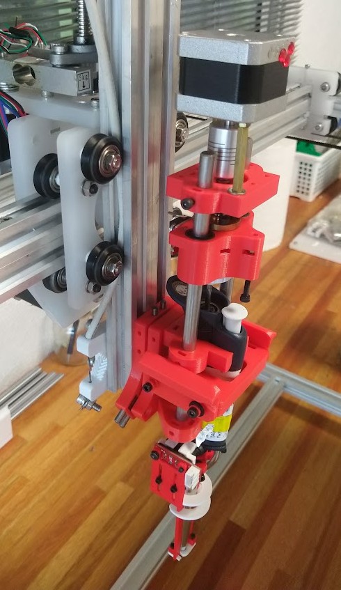
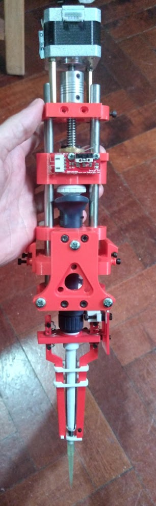
This documentation page is relevant to the design and construction of an electronic micropipette tool, based on existing manual micropipettes (i.e. for humans).
Many labs will have these micropipettes, and also calibration services they can rely on. These are the main advantages of the approach.
Usage
Use these tools to transfer liquids in the range of the micropipettes:
- Tip placement and ejection (in the trash bucket, or put back in the box).
- Regular pipetting: aspiration, dispensing, and blow-out, repeat.
- Serial dispensing: single aspiration, and repeated dispensing of low volumes, reload, repeat.
Danger
Never put your hands in the tool's carriage or in the robot while the pipette is in use. The motors will not stop until their reach their target, and it might stab you with a tip. We are not liable for the use you give to the robot, as we provide this documentation with no guarantees of any kind.
Calibration:
- The pipette's shaft was measured with a caliper, which requires disassembling it.
- Due to the weight of the water column in the tip, a correction factor must be applied, slightly increasing the shaft's displacement (per unit volume) to compensate.
- Gravimetric calibration is difficult at low volumes, and surface tension effects interfere with it. Try calibrating it by serial dispensing into tubes with some volume in them. Repeat for several dispense volumes, discarding the first and last dispenses always.
Limitations
There are a few minor limitations:
- The actuator must engage the pipette's plunger before doing any work, which means that a small loss of range is inevitable.
- Another slight loss of range is caused by the same uncertainty about the true position of the first stop of the pipette.
- Servicing the pipette requires disassembling the actuator, sending the pipette to your local service center, re-asemmbling the actuator, and re-calibrating a few tool parameters.
- Don't panic! You can avoid most of this hassle by servicing the micropipette yourself. For this you must source replacement o-rings, PTFE seals, and tip holders, which are the parts that wear out more frequently.
Assembly
Assembly and manufacturing:
- Document type: Technical documentation.
- Required resources: parts, tools, environment, and skills required to build the project.
- Audience: Makers, Users.
- Content: Bill of Materials (materials and parts). Full description of assembly steps, parts, required knowledge, skills, time, and tools. Manufacturing instructions for custom parts, shopping list for comercially available parts and possible suppliers.
- Precautions: Indicate if there are any precautions that must be taken.
Step 1: Print the parts
- Download the FreeCAD models from the main repository.
- Open the adapter's assembly file
AS-GIL-JUB.Fcstd, and export the parts to STL format, inlduing the parking post. - Arrange the parts in your slicer, and print them in PLA (or plastic of your preference).
- Optional: export and print the models for the tip probe (e.g. p20:
AS-GIL-TIP-PRB20.V1) in theGIL-TIP-PRB.Fcstdfile.
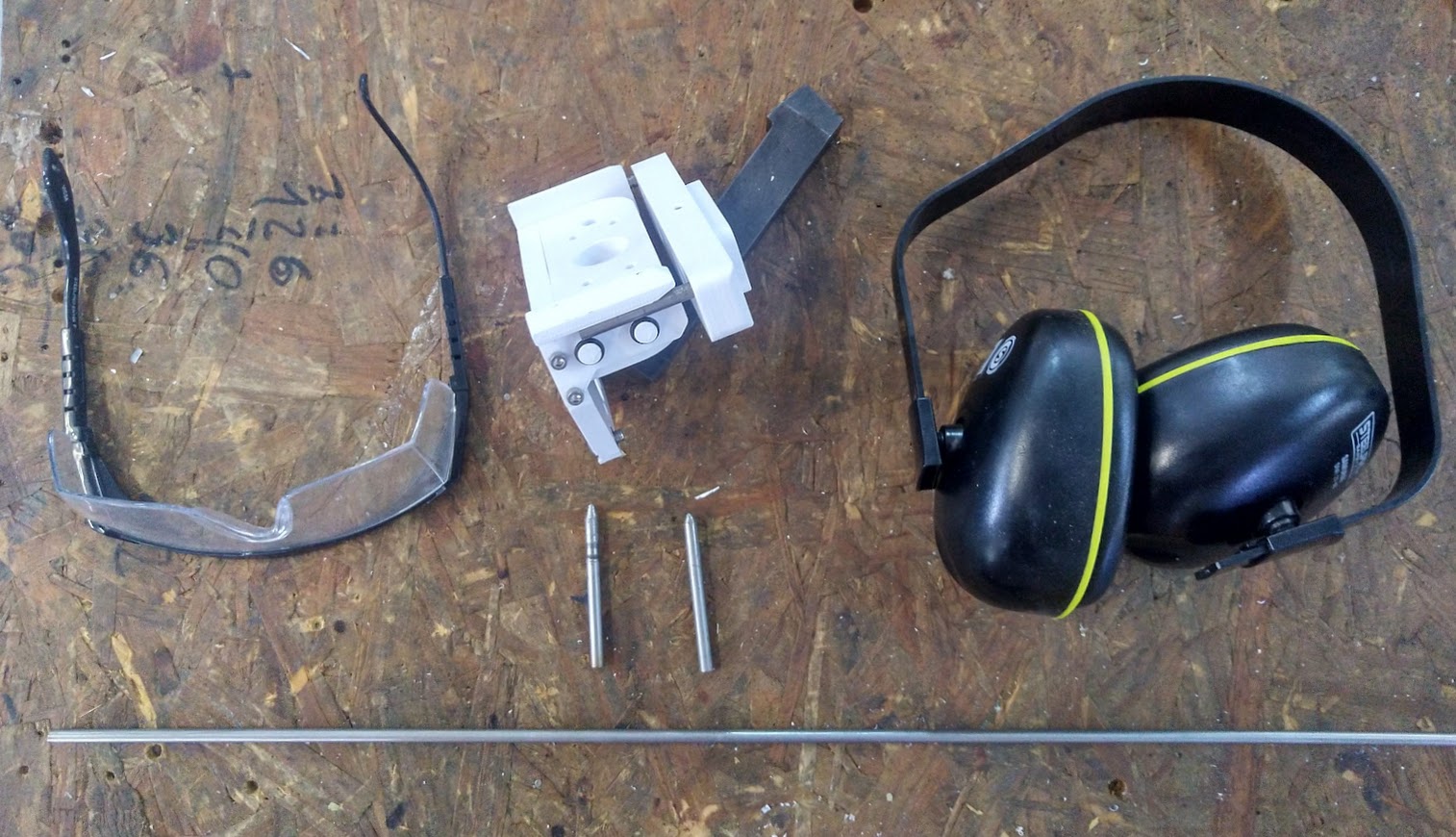
Step 2: Prepare parts
- Cut to pieces of 8 mm OD rectified steel rod, each at least 170 mm in length.
- Cut a piece THSL lead-screw (2 mm pitch, 8 mm diameter), 40 mm length. Remove any burr from the thread using a file, "Dremel" tool, or bench grinder.
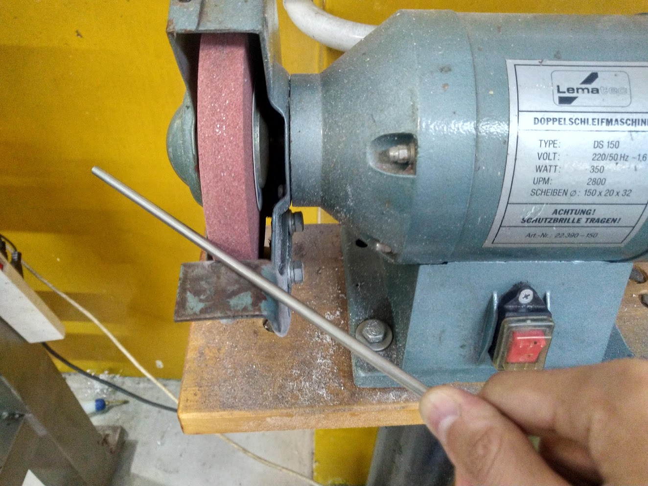
- Cut two pieces of 5 mm steel rod, each at least 62 mm in length. Chamfer one end of each rod to make them conical, by grinding with a bench grinder.
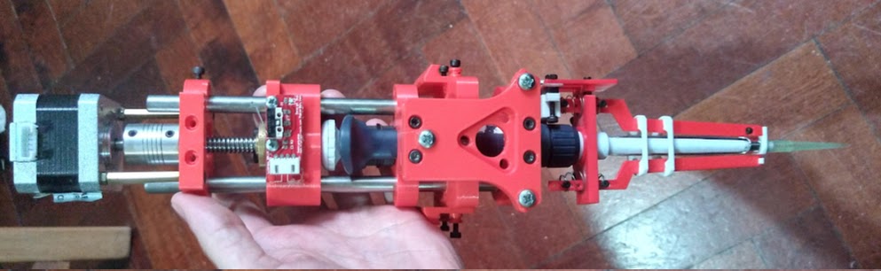
Step 3: Assemble the adapter
Warning
This guide is very rough. A coarse assembly sequence follows.
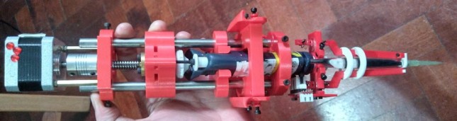
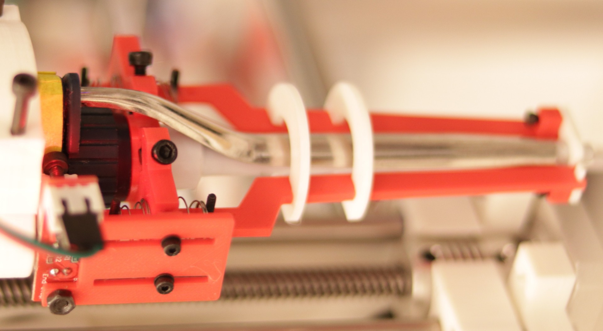
- Assemble the actuator's carriage, including the 3D-printed part, THSL nut, end-stop switch, and LM8UU bearings (these are press-fit into place). Don't forget the long M3 screw that will press the tip ejector button on the pipette.
- Attach the rigid coupling to the stepper's shaft, and the THSL leadscrew to the coupling.
- Attach the stepper to its base using 30 mm "tower" separators, and short M3 screws (not four). Add a fourth 40 mm M3 screw to the remaining corner (this one will trigger the endstop on the carriage).
- Attach the tool-parking wings to the U-shaped 3D-printed part. Add 2x6 o-rings to each wing.
- Attach the THSL wedge plate to the toolplate.
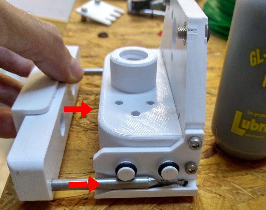
- Attach 3D-printed adapter parts to the micropipette; one just above the tip holder, the other just above the handle.
- Align the two adapter parts to the tool-plate. Insert "prisoner" M3 nuts intro the corresponding slots, and attach the parts to each other with M3 screws.
- Insert one of the rods through the top adapter part, then through the U-shaped part, and then down into the second adapter part. Repeat this sequence to insert the second rod. Adjust the height of each part until it looks nice.
- Insert the two free ends of the rods into the stepper motor assembly.
- Add M3 nuts to all slots, and tighten everything into place with short M3 screws.
- Adjust the height of the endstop-trigger screw.
- Adjust the height of the ejector-pushing screw.
Tip
To make this into a Jubilee-compatible tool, you only need to replace the THSL wedge-plate with Jubilee's wedge-plate.
The process involves adding heat-set inserts to the tool's plate, and then securing the new wedge-plate with screws. You can follow Jubilee's instructions for further detail (see page 2 of the instructions for the Bondtech Direct Drive Extruder).
After this, you'll need to modify our parking post with wire cutters to insert it upside-down, and then adjust the height of the tool relative to the tool-changer, by playing with the set screws that hold the tool wings to their height (IOU better instructions).
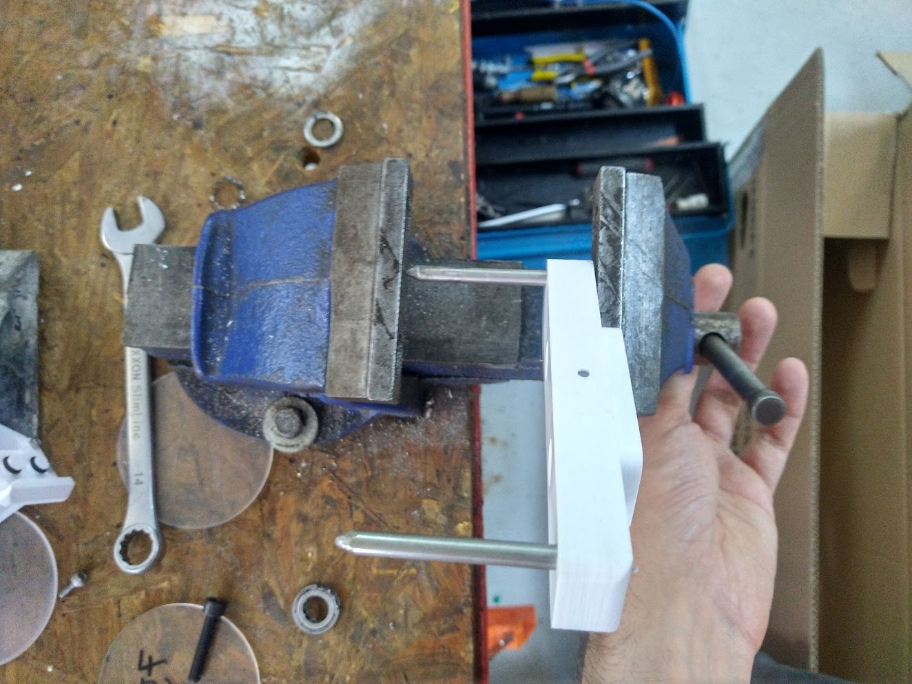
Step 4: Parking post
Warning
This guide is very rough. A coarse assembly sequence follows.
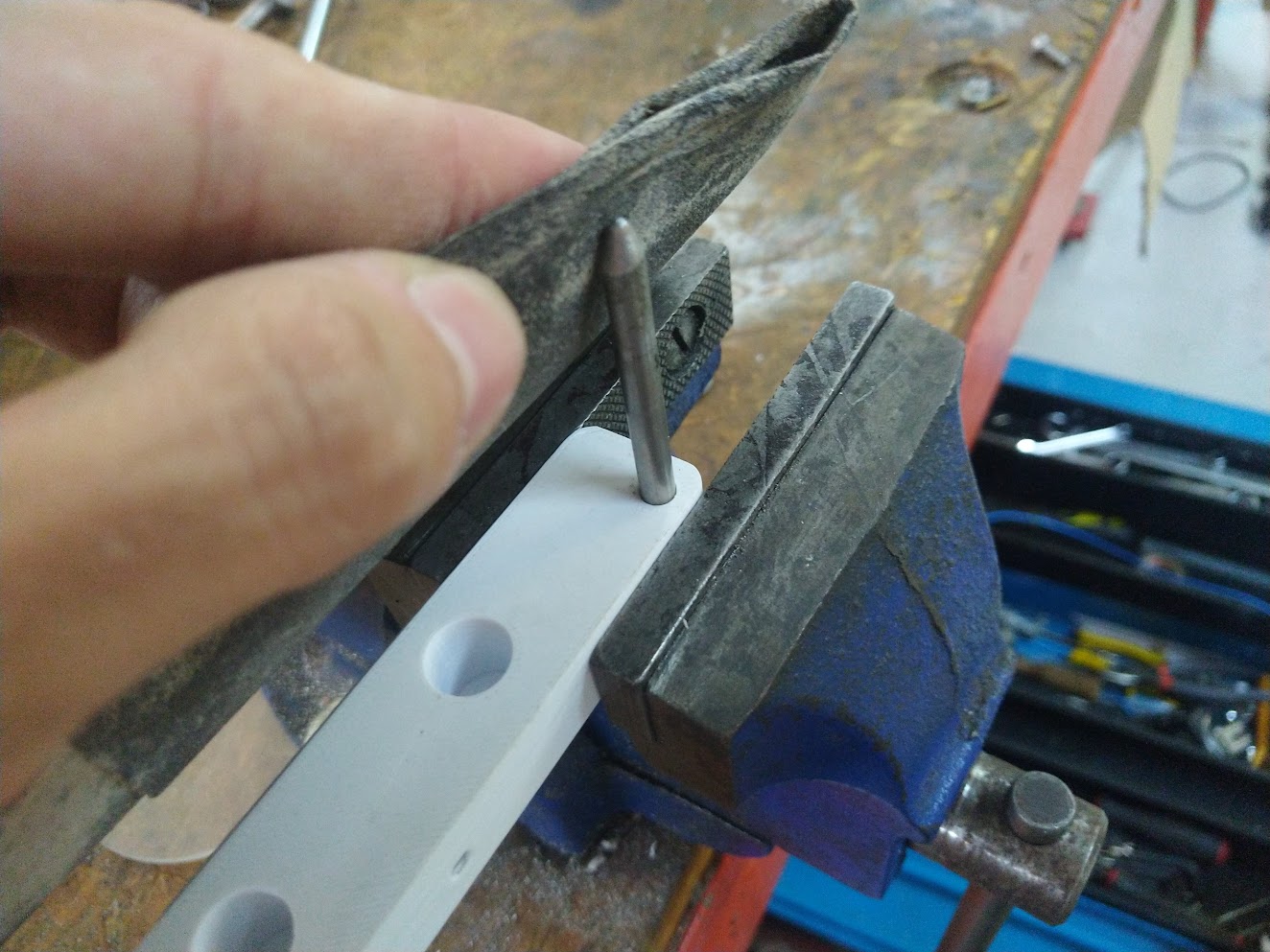
- Find a 2 mm or 3 mm drill bit.
- Insert the 5 mm rods into the parking post.
- Slide the parking post into the pipette tool, on the side contrary to the tool-changer plate.
- Place the whole assembly against the back-panel, and find a place for the tool to park, by moving it around.
- Make sure that it will not make collide with other objects when being parked or picked up.
- Keeping the post firmly in place against the back-panel, remove the tool, without disturbing the post's position.
- Use the drill bit to make a mark on the back-panel, by passing it through one of the mounting holes.
- Set aside the drill bit and the post.
- Use a drill to make a 4 mm hole on the back-panel where the mark is.
- Attach the post to the back-panel with an M4 screw and nut.
- Rotate the post until it is level, and make a mark for the second hole.
- Turn the post out of the way, and make the second mounting hole on the back-panel, where the second mark is.
- Fix the post to the back-panel with another M4 screw and nut.
Warning
The images below are from an old model of the pipette tool, but the same operations apply.
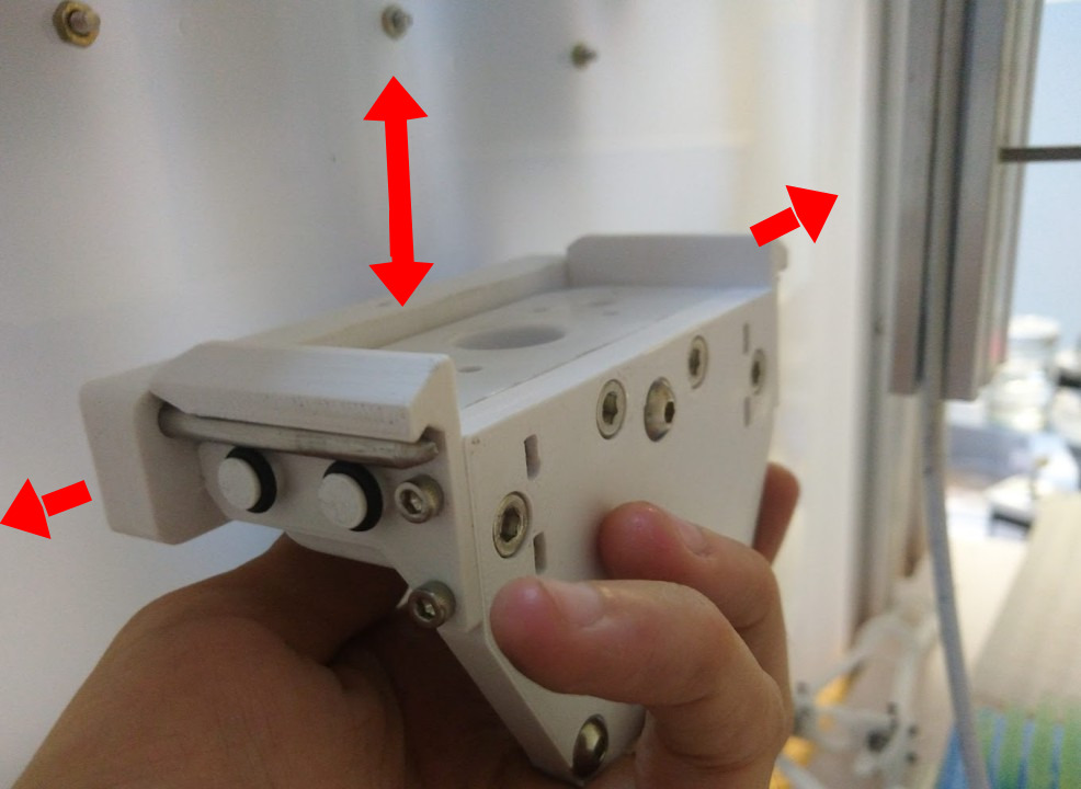
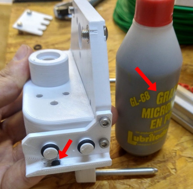
Optional:
- Turn the tool upside-down.
- Add a small amount of graphite powder to the grooves in the tool-parking wings, and spread it around.
- Clean the excess.
Warning
The images below are from an old model of the pipette tool, but the same operations apply.
Optional: Tip sensor
The tip sensor allows the tool to know when a tip has been inserted at the correct height.
Warning
This guide is very rough. A coarse assembly sequence follows.
Note that the assembly requires that you insert "prisoner" M2 nuts into several slots of the 3D-printed parts at certain moments.
- Print the parts.
- Fit the stalks to the the end piece (small, S-shaped), and secure with an M2 screw from the top side.
- Mount the opto-endstop to its plate, and mount the plate to the base.
- Slide one conical spring into each stalk, slide the stalks into the base, and add springs from the other side.
- Compress the springs by inserting M2 screws on both sides of the stalks. Choose the holes such that the stalk assembly "floats", and can move up and down freely between 1 cm and 2 cm.
- This completes the sensor assembly.
To attach the sensor to the micropipette:
- Remove the tip ejector from the micropipette.
- Slide the tip holder through the large hole in the sensor's base part.
- Slide the tip holder through the end of the tip ejector.
- Slide the tip holder through the end part of the tip sensor.
- Fit the tip ejector back into the micropipette.
- Slide the sensor assembly upwards or downwards, until the end-piece floats about 1 mm from the end of the tip holder.
- Lock the sensor into this position through its base, using a pair of M2 screws.
- Test that the sensor works by inserting a tip until it seals perfectly, checking that the sensor slides upward at the same time, but does not reach the end of the tip ejector.
- Then eject the tip by manually pressing the ejector button. Check that the sensor's end piece does not come off the tip holder's end, and that it slides upward when the button is released, back to its original position.
- Repeat steps 8-9 several times, until you are confident that tips can be placed and ejected correctly, and that the sensor does not "fall out" of the tip holder.
- Energize the opto-endstop, and place a tip. The LED will turn off when the end-stops optical gate is triggered by the tip sensor's stalk.
- Slide the sensor's base upwards or downwards, such that it is barely triggering the endstop when the tip is placed to the correct depth.
Installation
Hardware and software installation instructions:
- Document type: Technical documentation.
- Tools and skills: tools required to install, setup, or calibrate the hardware and or software.
- Audience: Technical support, Makers, Users.
- Content: Complete description of installation steps and required knowledge, environment, number of people, skills, time, and tools. Links to learning resources. This applies to installation of software (e.g. OS, compilation, dependencies, drivers, etc.) and hardware (e.g. location requirements, operating conditions, etc.).
The tool is used by the robot only if it has been configured and calibrated.
It may be a good idea to do a gravimetric calibration before using it with the robot, to check that everything is working properly.
Interactions
Interfaces and interactions:
- Document type: Technical documentation.
- Audience: Makers, Users.
- Content: Indicate how it connects to other parts of the robot, and all parameters relevant to those interactions and/or interfaces. Also comment in which section of the documentation you think your material goes (Assembly, Maintenance, Design, Development, etc.).
Maintenance
Maintenance procedures:
- Document type: Technical documentation.
- Audience: Technical support, Users.
- Content: Required maintenance operations, frequency, tested replacement parts and compatible alternatives.
- Precautions: Indicate if there are any precautions that must be taken.
Every few weeks, check the lead screw for proper lubrication and cleanliness.
Design
Range loss:
Con los adaptadores de pipetas manuales, siempre perdemos un poco de rango.
Esto es porque no es fácil estar 100% seguros de a qué "altura" el actuador empieza a empujar el émbolo, y lo mismo para el segundo tope.
Actualmente considero que la p200 tiene 150-180 uL de volumen útil (en vez de 200 uL).

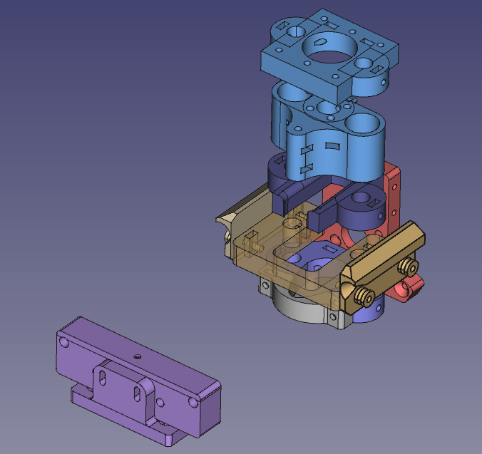
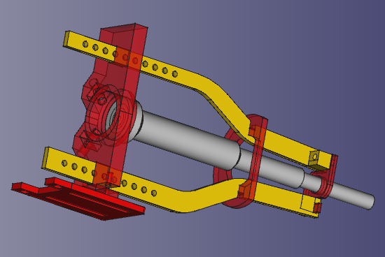
Models
Hardware design files:
- Document type: Source files.
- Audience: Developers, Contributors.
- Content: Design files with parts metadata, typically including: mechanical models (e.g. FreeCAD), schematics for electronics (e.g. KiCAD), technical drawings, specifications of parts and materials, etc. Distinguish between custom parts (e.g. developed as a result of this or another project), off-the-shelf parts (e.g. screws), or complex modules (e.g. a single board computer). Specification for all hardware interfaces.
- Explanation of the part-naming scheme/convention.
FreeCAD files:
Software
Software and firmware sources:
- Document type: Source files.
- Audience: Developers, Contributors.
- Content: Original computer code for the programs required to operate the machine to its full capability. Detailed instructions to build and/or install the software and its dependencies and their specific versions. Specification for the programming interfaces (APIs) if any.
Relevant sofware:
- Piper plugin for the micropipette adapter tool: https://gitlab.com/open-la/pipettin-piper/-/blob/master/piper/plugins/pipettes.py
Development
- Document type: Technical documentation
- Audience: Developers
- Content: Development flow and tools (e.g. IDEs, EDA, or CAD software), file formats, and guidelines used to develop the project. Description of setups for development and testing. Detailed description of the hardware modules and software, and corresponding source files. Tutorials and examples for how to get started or adding new modules.