Tool Changer
Tool-changer
Info
Discord forum thread: Tool-changer License: CERN-OHL-S-2.0
Overview
The tool-changer is a system that allows tools (in our case a micropipette) to be mounted reversibly to the Z-axis.
It consists mainly of two main mechanical parts:
- The docking interface: we re-use E3D/Jubilee's interface, a Maxwell kinematic coupling.
- The locking mechanism: this is a custom REL (remote elastic lock), inspired by Jubilee's, but redesigned with simplicity in mind.
- Active mechanisms use a motor (such as ours and Jubilee's).
- Passive mechanisms do not (e.g. Pipettin Zero's, Prusa XL's, and DAKSH-V2's tool-changer systems).
Throughout this section you will find general guidelines for building the Pipettin bot's tool-changer, such as the tool-changer's drawings, manufacturing instructions and other options and ideas you could consider for your Pipettin bot.
Demo video
Usage
Assembly
Note
The remote actuator is mounted on top of the Backpanel, and the head plate on the motion system's Z-axis. You may assemble parts of the toolchanger intedependently, but you will need to follow those guides to complete this one.
Stepwise guide
A nice and updated step-by-step guide for the assembly is available:
- Remote actuator: https://stepwisedocs.com/docs/projects/olas-mk3-4/guides/tool-changer-remote-40
- Headplate: https://stepwisedocs.com/docs/projects/olas-mk3-4/guides/tool-changer-head-plate-41
Instructions below can be considered development notes.
Manufacturing
Required skills and resources
As other systems, you must have access to a 3D printer. All custom parts were printed in PLA; better materials can be used.
Other option is to make metal (or plastic) pieces with a CNC router (or laser). It will be more expensive, and require several operations. The advantage will be increased rigidity, stability, and longevity.
Step 1: Gather parts
Gather materials, tools and parts: https://pipettin-bot-d7af10.gitlab.io/toolchanger/parts-toolchanger.html
TO-DO
Add picture of all required parts and tools.
Step 2: Bevel the lead-screw
Tools:
- Bench grinder.
- Angle grinder.
Steps:
- Wear protective equipment (glasses, gloves, etc.).
- Cut a THSL screw to 36 mm length using the angle grinder, with a vise to hold it in place.
- Bevel one end of the screw using the bench grinder.
Step 3: Assembly
Step-wise instructions:
- Remote actuator: https://stepwisedocs.com/docs/projects/olas-mk3-4/guides/tool-changer-remote-40
- Headplate: https://stepwisedocs.com/docs/projects/olas-mk3-4/guides/tool-changer-head-plate-41
Interactions
The tool-changer is connected to several other parts:
- Motion system z-axis: attached to its profile with some nuts and screws.
- Micropipette tools: through a kinematic coupling and locking thread on the tool-plates.
- Backpanel: where the remote actuator is attached.
- Structure: the guide for the tool-changers cable is attached to the top of the structure.
Parking "tool-posts" are mounted on the back panel, but this interaction is not direct.
Maintenance
Tool-changer failure may result in malfunctions and equipment damage.
Regularly clean and lubricate the tool-changer's remote actuator, to ensure the proper functionality of its moving parts.
Additionally, inspect the cable guide for damage and wear. Consider adding a small amount of lubricant to the inside of the cable guide, or replacing it entirely if you observe signs of accumulating damage.
If any 3D-printed components are broken or deformed, they can be reprinted. Heat from stepper motors will damage or deform 3D-printed parts.
Screws may become loose over time. Check the remote and headplate to ensure that they are tight every now and then.
Design
One of our goals was to design something as simple and compact as possible, minimizing space occupancy and allowing for maximum freedom of movement along the Z-axis.
Our tool-changer is based on Jubilee's tool-changer, with some essential changes, for compatibility between these open-source CNC machines.
Head plate
We have borrowed Jubilee's tool-changer, based on the concept of a Remote Elastic Lock (a.k.a. REL).
- The motor drivin it isn't mounted on the tool-changer (is 'remote').
- Constant holding torque (is 'elastic').
- Admits some mis-alignment (± 1 mm for Jubilee, ± 0.5 mm for ours).
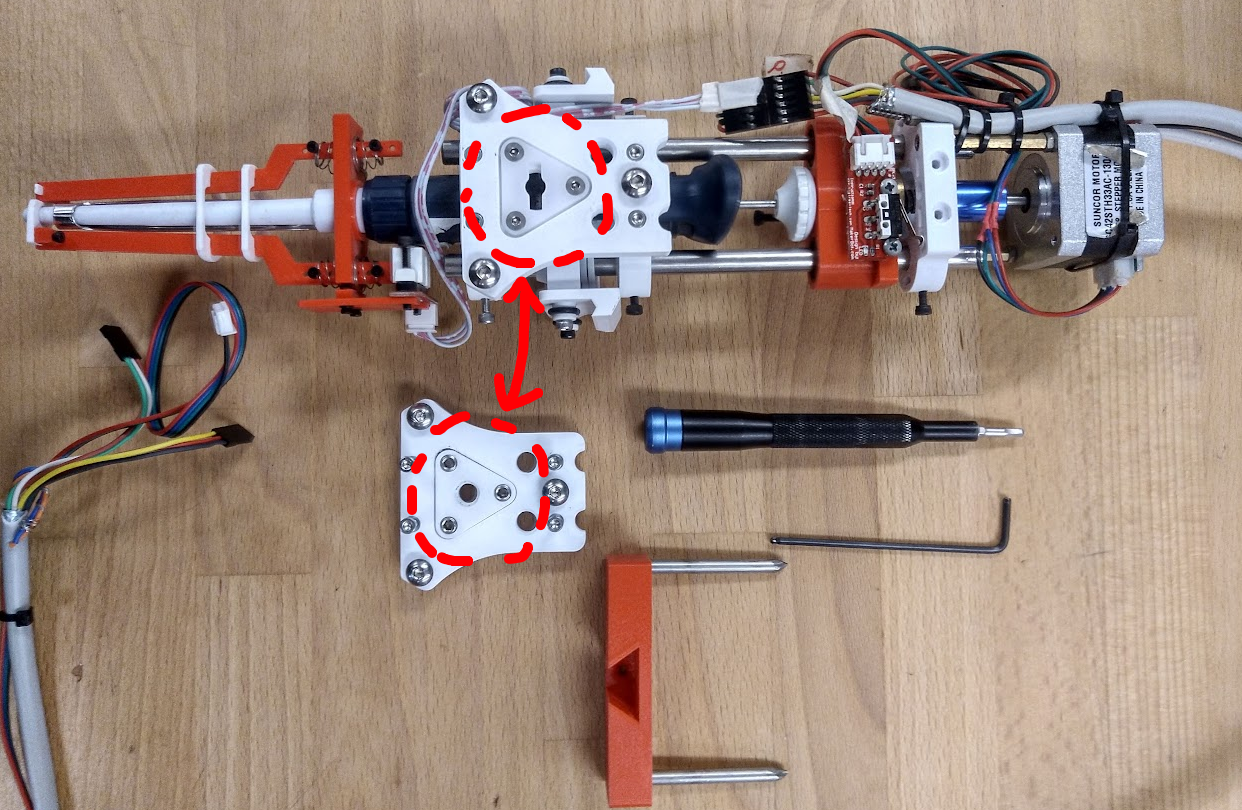
We wanted to create a system that retained interoperability with Jubilee's tool-changer, but did not depend on any machined parts (e.g. its cross-bar). With that in mind, we arrived at a design whose only breaking change is an exchangeable "wedge plate" on the tool side.
Jubilee's wedge plate is the "keyhole" of its locking mechanism, with a "cross bar" as the key. We have instead used a 3D-printed "THSL" wedge plate and a short leadscrew. These wedge plates are exchangeable, and easy to fabricate, making tools interoperable between both platforms.
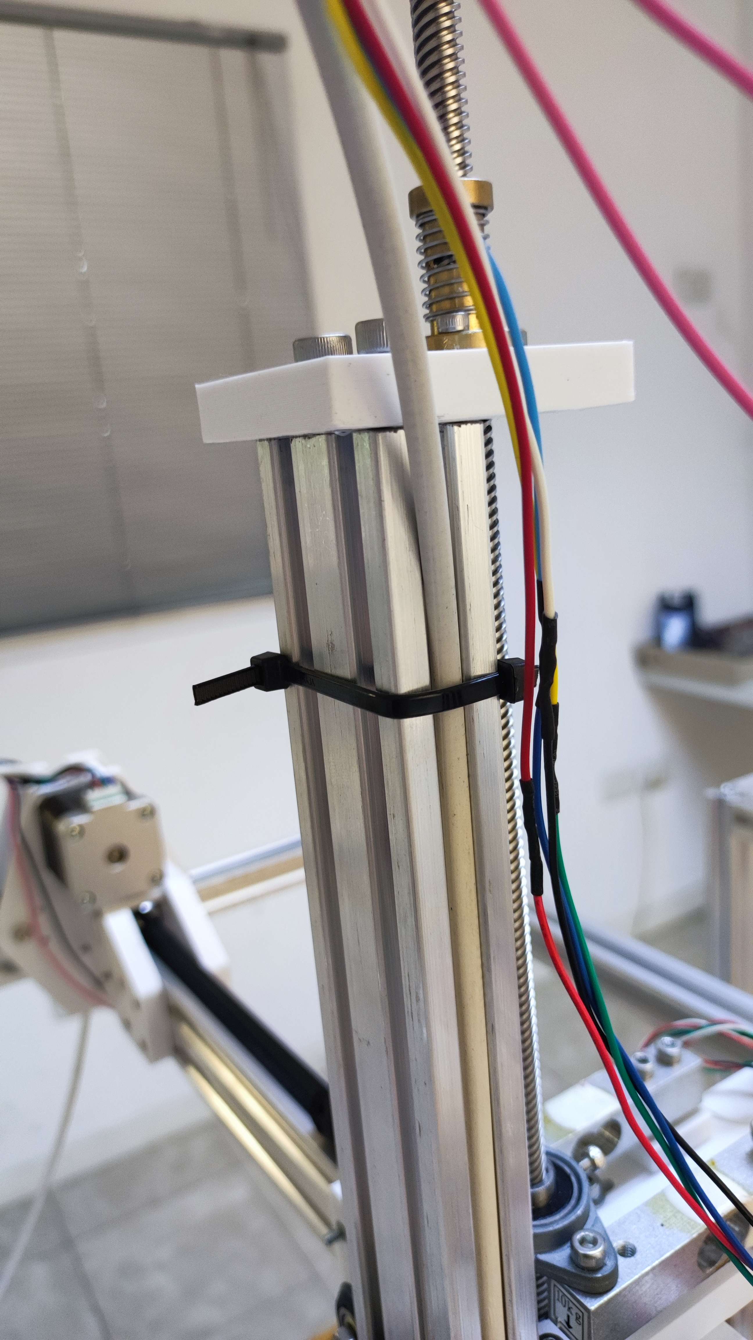
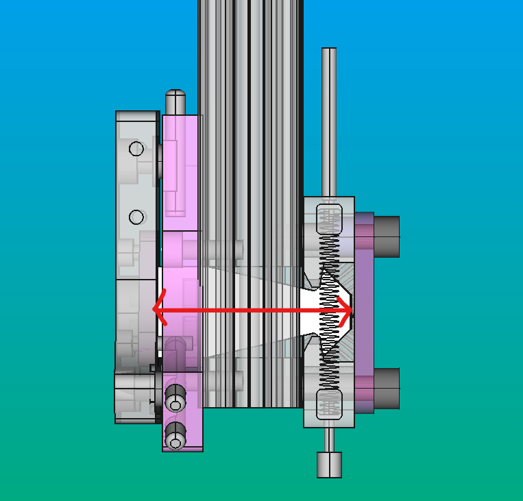
Beause our Z-axis moves, the tool-changer interface is placed on the bottom end of its 2040 profile. In our tool-changer, a spring within the extrusion keeps the lock engaged, providing sustained tension (akin to the 'normal closed' concept in electronics).
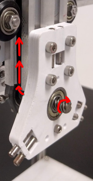
To park a tool, the tool is moved to its parking post and the lock is released by the remote actuator, which pulls from a Bowden cable anchored to the top of the Z-axis.
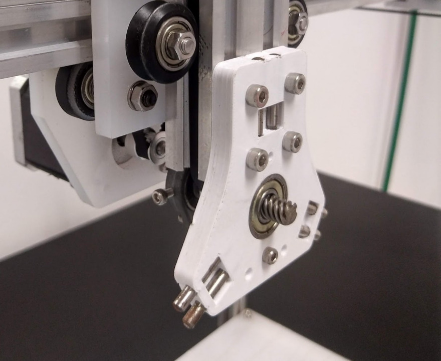
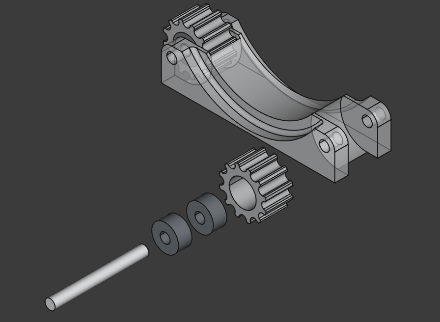
The main disadvantage of the design is in the idler pulleys that guide the TC's belt to the main pulley (image below). It relies on "mini" bearings and axles that may be difficult to source (e.g. only through AliExpress). You can, however, not use bearings at all and replace the axle with a 1.2 mm needle, at the expense of failures happening earlier, probably.
Remote actuator
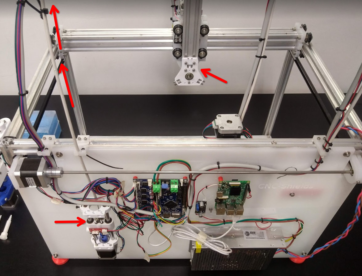
The tool-changer's actuator is remote, meaning that its motor is somewhere else. We have mounted it to the back-panel, to keep it close to the control electronics.
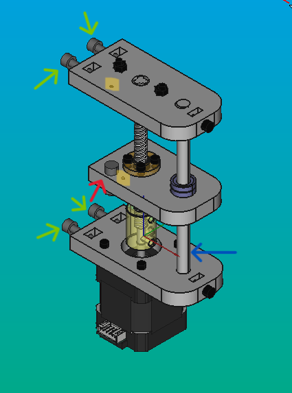
The remote has three important parts: the top and bottom bases, and the carriage.
The only piece that will have a degree of motion is the carriage (at the middle). This component is secured to the Bowden wire via a screw, and can pull from it by moving downward. Pulling on the wire will cause the tool-changer to unlock, while moving upwards will allow the tool-changer to unlock (pulled by its spring).
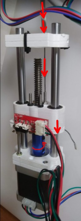
The base parts will be affixed to the electronic casing using four screws, rendering them immobile relative to each other. Otherwise, the motor would not produce any useful pulling force.
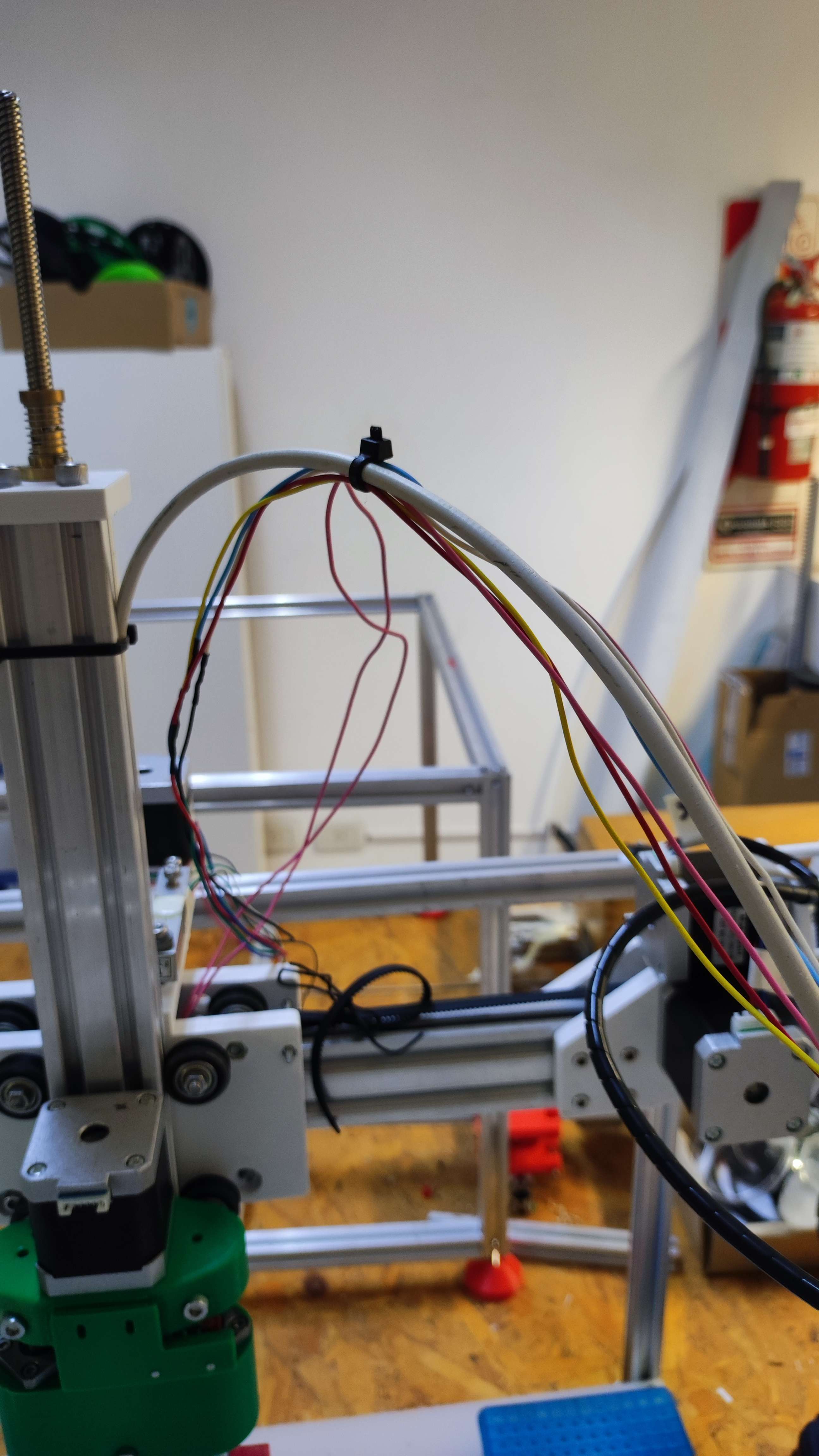
The motor is mounted on the "backpanel", and is thus remote, in order to save space and weight on the motion system. Its bowden cable carries the force to the head plate; it has one mount point on the remote, and another on the top of the Z-axis.
Tip
To manually release the lock, you can grab the bowden cable by hand at the top of the Z-axis, and pull upwards. Note that any loaded tools are likely to fall off, so make sure you catch them before releasing the lock fully.
Models
Links to CAD files listed in the sources page.
Development
These 3D-printed parts were designed in FreeCAD 1.0, and saved in the native FCStd format. Printable STL files were printed on an Original Prusa i3 MK3.
To learn more about these file formats visit here.
Legacy
Previous versions and design notes.
Key-based lock
- For the design of the 'KEY.V1':
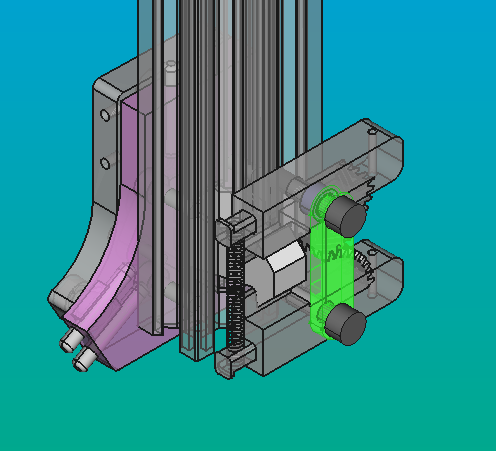
- The key has, laterally, the shape of an arrow (green lines). Thanks to this shape, it will engage between the teeth of the brake arm gears. These teeth need to have as close to a vertical angle as possible so that the resulting force from the interaction is primarily horizontal (red lines).
- On the other side, it will be secured to the key plate, which will be inserted into the tool plate using 2 M3 screws (yellow holes).

- The length of the key must take into consideration the width of the profile, the width of the brake arms, and the width of the head plate.
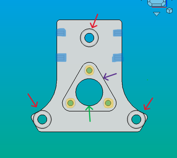
- For the design of the 'TOOL_PLATE.V1':
- This piece serves as the mounting point for the tools.
- It has three holes to connect the tool plate and the key using screws (yellow marks). Additionally, there are three holes for attaching round-headed screws for the kinematic system (red arrows).
- The tool parking wings are also located on the side (blue marks).
- The green hole is to facilitate the key assemble, and the triangle hole (in purple) is to put the keyplate.
- In future versions, it will have holes to prevent the tools from falling down (we're still working on it).
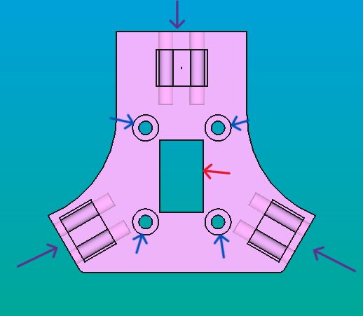
- For the design of the 'HEADPLATE.V1':
- It features a square hole for the passage of the key (red arrow).
- There are 4 holes for securely fastening it to the profile (blue arrows).
- Additionally, there are 6 holes for inserting pins to support the heads of the screws from the tool plate that are part of the kinematic system (purple arrows).
- For the design of the 'KEY_PLATE.V1':
- This piece connects the key with the tool plate. It is attached to both using nuts and screws.
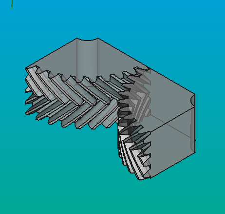
- For the design of the 'GEAR_H_DW29.6 + BREAK_ARM_GEAR'
- This piece is the one that engages the key and ultimately holds it.
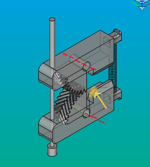
- It has a gear to coordinate the opening between both teeth (Δx/Δt same for both arms, green arrows). The parameters of the gear were adjusted until the separation between the two axes was sufficient (red arrow). It also has that shape to withstand higher pressures.
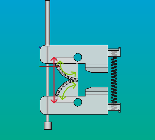
- The center of this gear is the axis around which the brake arm will move (red lines). The axis will be a screw, and by using a nut, it will help attach the brake arm to the profile.
- The tooth has a cut so that, during the opening, the key can pass through completely (yellow marks).
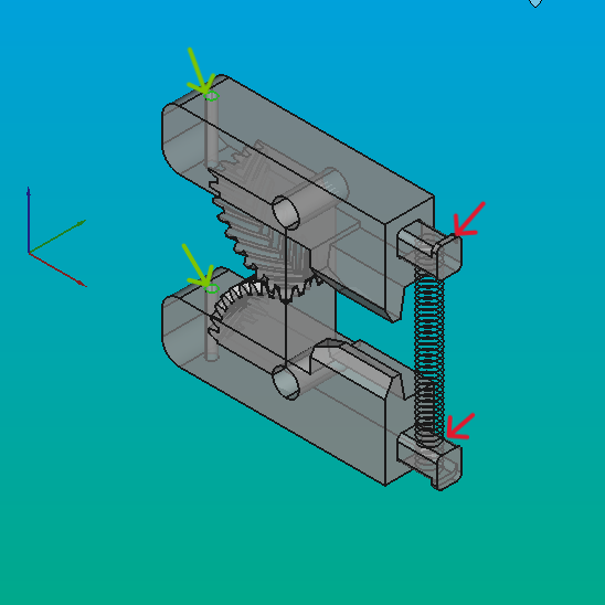
- At one of the ends, there is a protrusion (red arrows). This will be used to place the spring. Its size can vary depending on the type of spring and how easy it is to handle.
- At the opposite end, there is a through-hole where the cable of the sliding cable will pass through (green circles). The thickness of the brake arm must be wide enough to withstand the pressure generated by the spring and the cable. Due to this, it is also important that, if PLA is used, it is printed with a high infill (we print with a 90% infill), and that the hole on which the system will pivot, that is, where the screw passes through, is well-reinforced.
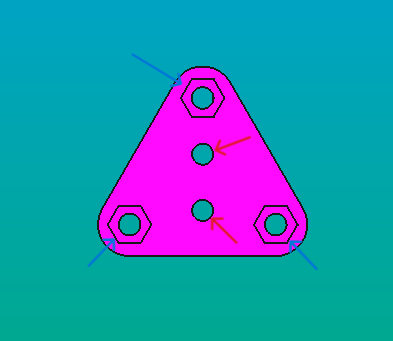
- For the design of the 'BRAKE_BASE.V1':
- This component adds stability to the system, preventing the teeth from separating when the spring expands (highlited piece).
Old motor base
We needed to create a system for remote control of the actuator. To achieve this, we considered utilizing a mechanism that pulls the internal wire of the cable, similar to a pulley system, as explained earlier.
The motor base is affixed to the back panel, and we secured it using nuts and screws on the top with the top.v1 and base.v1 parts (indicated by the green arrows). Additionally, we incorporated a template road to enhance stability (blue arrow).
The cable wire will pass through the holes marked in yellow and will be secured with the screw indicated by the red arrow in the image
The cable used will extend to the tool changer actuator through the guides of the profiles, and it will also assist in routing the electronic cables towards the Z-axis.