Tool Parking Posts
Parking Posts
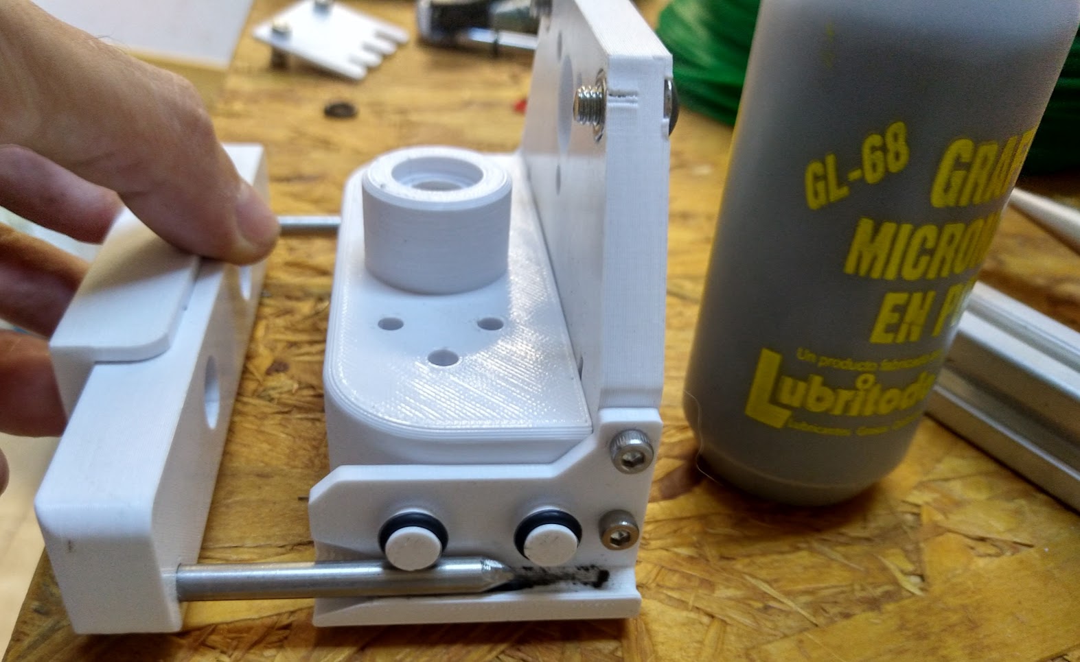
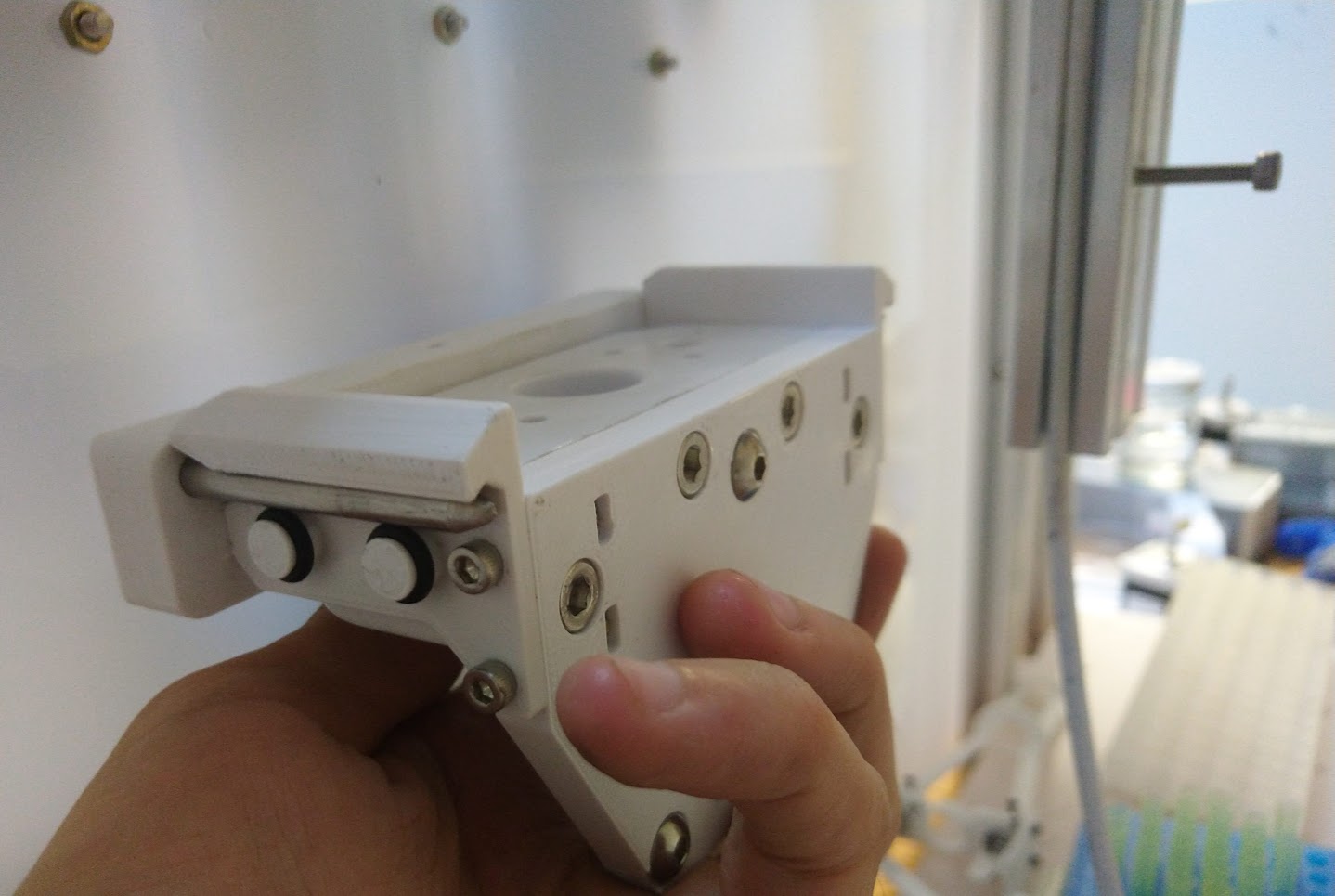
A parking post is a mechanical system where tools can be stored and picked-up, much like a "pegboard" for shop tools.
Warning
Slightly outdated content.
Overview
The "parking post" is the place where the tool-changer can "park" a tool when it is not in use, and also can pick it up from there when it is needed.
Throughout this section you will find general guidelines for building the Pipettin bot's tool-parking posts, such as the technical drawings, manufacturing instructions, and other options and ideas you could consider for your Pipettin bot.
These parking posts are derived directly from Jubilee's.
Usage
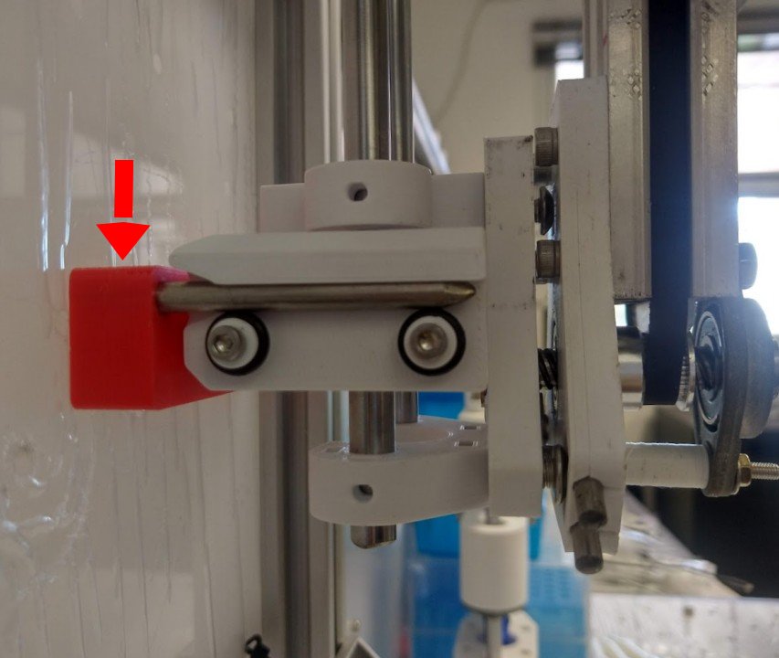
Our tool-changer is based on Jubilee's Tool-parking (part PPB47-05), but we implement some changes: the current one will be mounted on a vertical surface, while the Jubilee version is designed for a horizontal surface (on a 2020 profile). Additionally, it was adapted to the size required by the pipette.
The tool-posts are mounted on the Back-panel, and attached to it with some screws. The location of the post can be anywhere you want, as long as the tool can be reached by the tool-changer, and does not crash into anything during the tool-changing sequence.
Assembly
Warning
This guide is very rough. A coarse assembly sequence follows.
Step 1: Print parts
Parts and materials:
3D-print:
- 1x PIP-PARK-BASE.V1
- 1x PIP-PARK-HOLDER-107.V1
Of-the-shelf parts:
- 2x CAP_SCREW_D5
- 2x M5-30-PAN
- 2x M5-NUT
Tools for assembly:
- screw driver
3D-print:
- Parking post base part: common to all tools.
- Tool adapter for the base part: each tool may require an adapter of a certain width.
Due: part links for each tool/length.
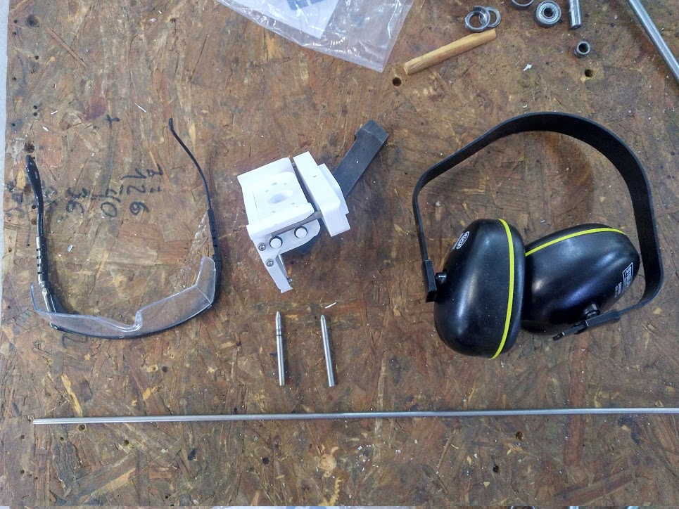
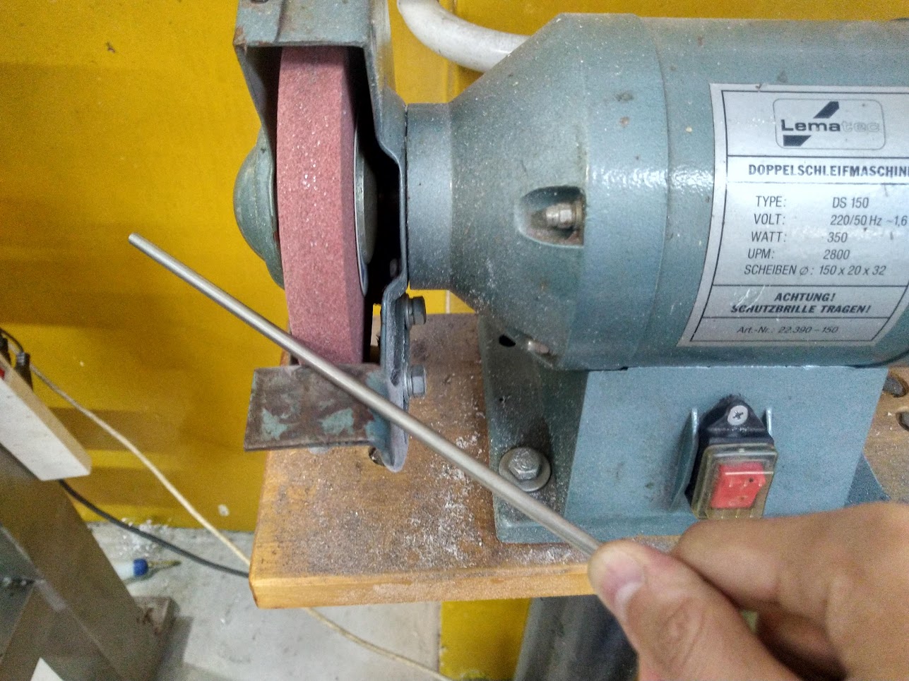
Step 2: Cut pins
Cut:
- Parking pins (5 mm rods): each tool may require pins of a certain length.
Due: dimensions for each tool/length.
Materials and safety elements to cut the pins with a bench grinder:
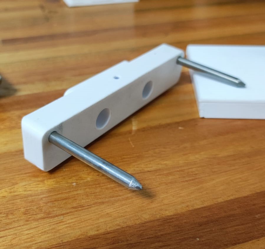
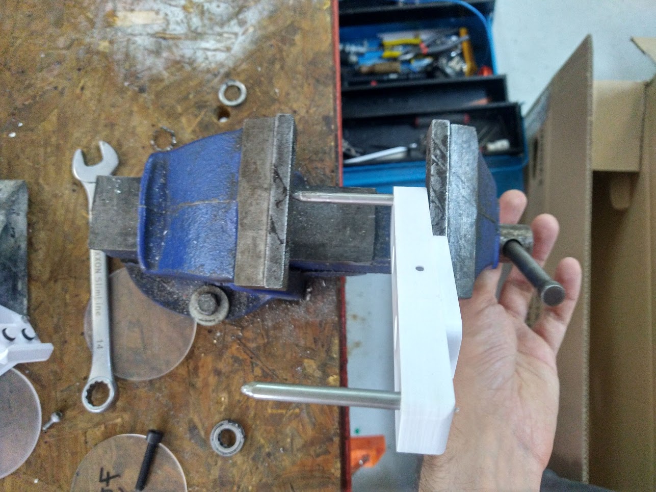
Step 3: Insert the pins
Press-fitting and sanding the pin
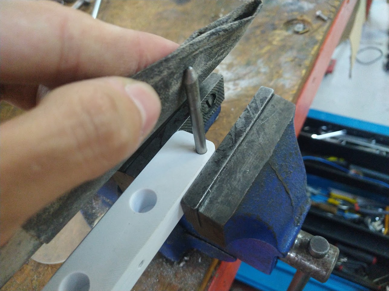
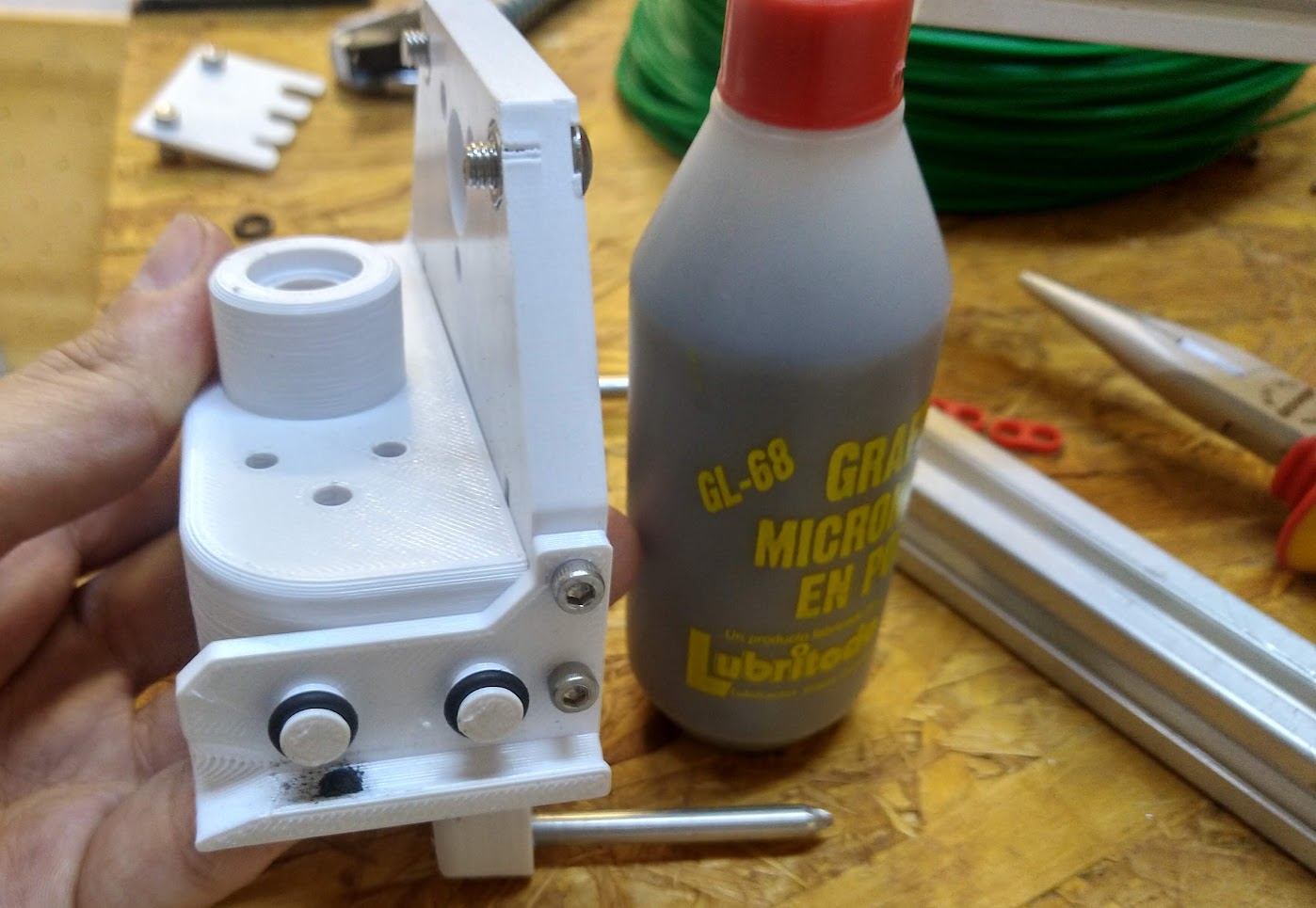
Add graphite powder to the 3D-printed part as lubricant
Installation
In this section you will find general guidelines for installing the tool-parking posts on the back-panel.
Step 1: Choose a location
Choose a location for the tool-parking posts.
Here are some suggestions:
- The spot must allow the tool to be parked and picked-up without collisions by the tool-changer. You can evaluate this by hand.
- Its cables or other components of the parked tool must not be in the way of the machine or other tools and objects in the workspace.
- This can be tested by placing the tool in the spot, and moving other tools around. Check if the cables become tangled.

Step 2: Mount to the back panel
There are two alternatives:
- There are pre-drilled holes on the back-panel, so you can use them to mount the tool-parking posts.
- You can also drill your own holes, as long as there are no electronics on the other side of the backpanel.
Warning
When drilling holes, make absolutely sure that there are no electronics on the other side of the backpanel.
If you choose to drill your own holes, you can do it in several ways:
- Design the holes into the back-panel, and laser cut them.
- Drill a single hole on the backplate, mount the parking post. Adjust its angle and only then tighten the screw, and then drill a second hole parallel to the first, using the hole of the parking post as a guide.
- Drill a single hole on the backplate (e.g. M4), then drill a slightly larger hole on the back-plate (e.g. M5), roughly parallel with the first. Mount the tool base, tightening only the screw of the smaller hole. Adjust the angle and only then tighten the screw from the wider hole.
Interactions
As we mentioned before it is connected to many parts:
- To the backpanel: It will be positioned on the internal side of it
Due: add screenshot or photo of tool-parking mounted on back-panel freecad
- To the tool: it will support the tools when they are not in use
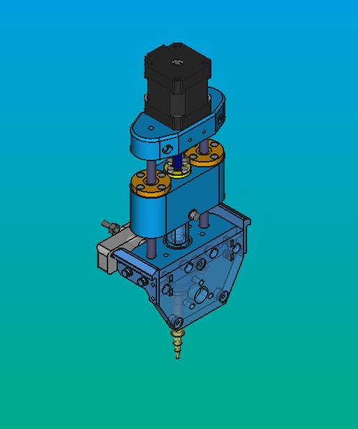
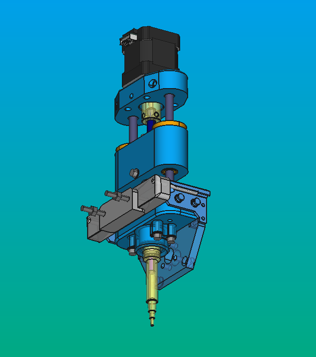
- To the tool-plate of the toolchanger: this connection enables the interaction of the tool parking system with the tool and the tool changer. Each tool will have its associated tool-plate, respecting the dimensions of the tool. For instance, in our case, we use this tool plate for our Micropipette:
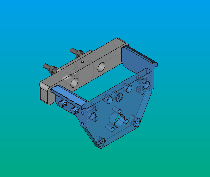
Info
All tool-plates share the same drawing base.
Maintenance
Daily, it is essential to clean the toolparking to ensure the proper functionality of its moving parts. Failure to do so may result in potential sticking.
If any 3D-printed components are broken or deformed, they can be reprinted.
If you added graphite powder to the 3D-printed part as lubricant, add it again as many times you need
Design
As we said before, we wanted to create a system that adapts to the Jubilee system, to be able to exchange tools without major changes. Based on that, we modify some jubilee's parts. One of our main objectives was to design something as simple and compact as possible, minimizing space occupancy and allowing for maximum freedom of the robot movement.
If you want to modify or create a new version of the actuator, you must have in mind the following:
- Our version is an adapted version of PPB47-05
- the current one will be mounted on a vertical surface, while the Jubilee version is designed for a horizontal surface.
- Additionally, I adapted it to the required size of the pipette.
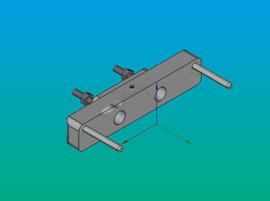
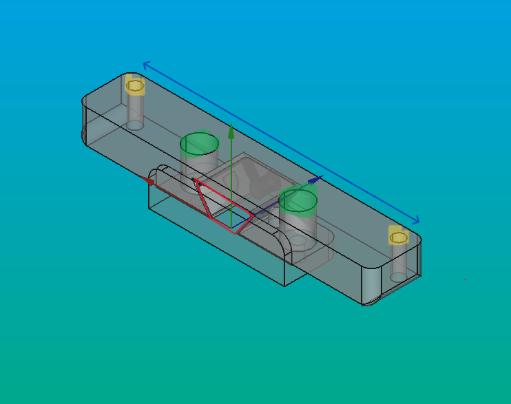
PIP-PARK-BASE:
- It has a trapezoidal shape to accommodate the PIP-PARK-HOLDER-107 piece in such a way that it has only one degree of freedom, upwards. This allows us to interchange the PIP-PARK-HOLDER based on the tools in use. On the image, red lines.
- The holes are designed for attaching it to the back panel. On the image, yellow zone.
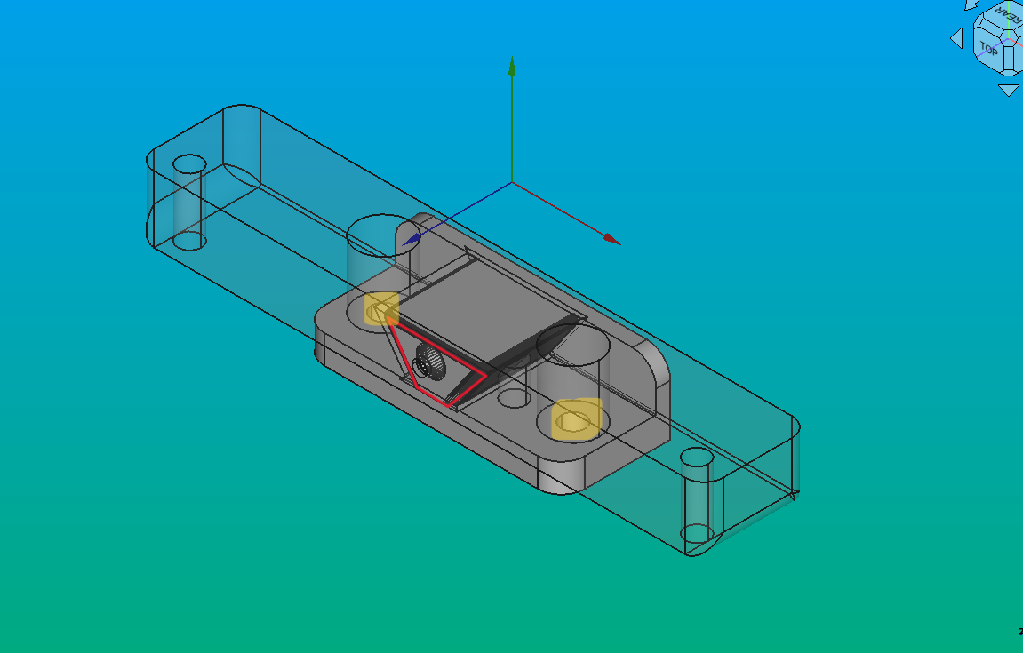
PIP-PARK-HOLDER-107:
- It features a trapezoidal slot to fit onto the pip-park-base. On the image, red lines.
- It includes small holes for inserting bolts, providing support for the tool. On the image, yellow zone.
- There are holes designed for attaching it to the pip-park-base, and an extra space to manipulate the screwdriver. On the image, green zone.
- You can change its large to adapt it to your tool. On the image, blue line.
Models
All hardware sources are available at the sources page.
Development
These 3D-printed parts were designed in FreeCAD 2.1 and 2.0, then exported in the FCStd format for slicing. They were printed on an Original Prusa i3 MK3 using STL files.
Most pieces were inspired by Jubilee's designs for compatibility between these CNC machines tools.
To learn more about these file formats visit here.