Structural Frame Assembly
Structural Frame
Info
Discord forum thread: Structure License: CERN-OHL-S-2.0
Overview
All of the Pipettin bots parts are assembled inside the structural frame, such as the baseplate and the carriages. Building the structural frame is the first step in the assembly process.
Throughout this section you will find general guidelines to build Pipettin bot structural frame, including the machining instructions and some helpful drawings.
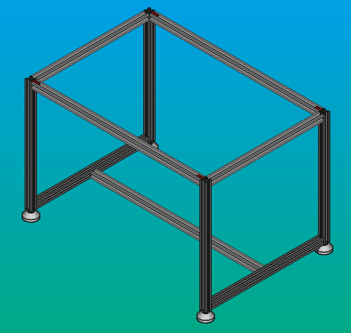
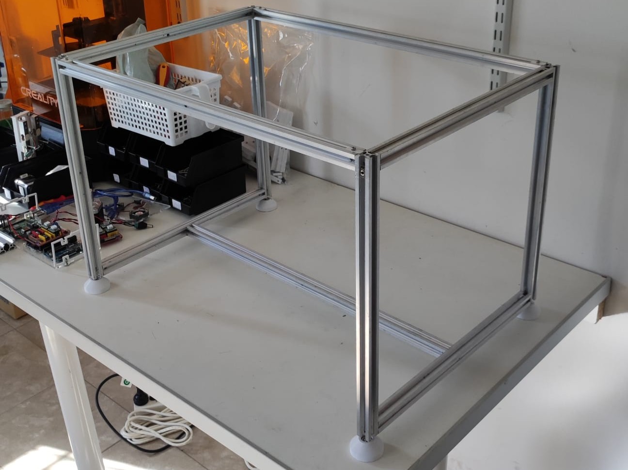
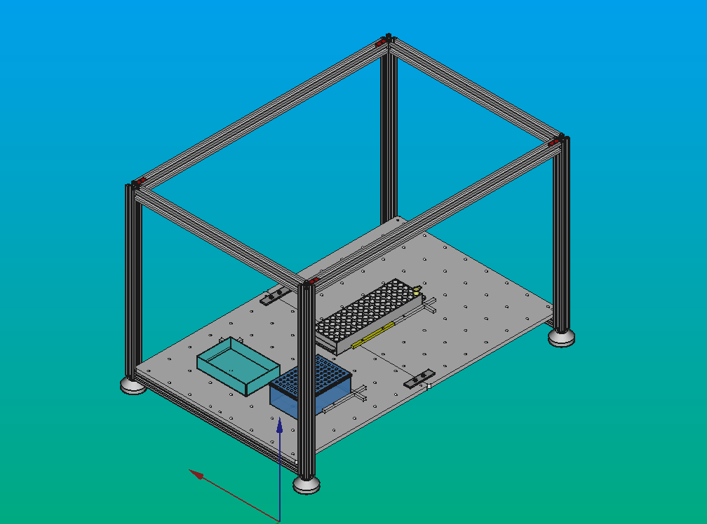
Expected result:
Usage
Warning
To ensure safe and secure transportation of the Pipettin Bot's structural frame, please:
- Grab the shorter profiles: Firmly grip the shorter set of profiles located on the top of the structure when lifting and carrying the frame. These profiles provide optimal stability and control.
- Avoid long profile manipulation: Refrain from lifting or twisting the longer profiles, as they are more prone to rotation under excessive torque, potentially compromising structural integrity.
- Prioritize gentle handling: Exercise caution and avoid applying excessive force or sudden movements to prevent any damage or misalignment of components.
Assembly
Assembly instructions are available at the stepwise guide.
Expected result:
Note
If you already have a cartesian 3-axis CNC frame from another machine (and know what you re doing) you can try using it instead  . The only requirement is that the Z axis is driven by a lead-screw (or belt) that can produce significant vertical forces. A GT2 belt can be used if there is a mechanical reduction between the stepper and the belt (e.g. with a ratio around 5).
Manufacturing
Manufacturing instructions for the structural frame.
Step 1: Gather parts
Gather all tools and materials listed in the BOM:
Step 2: Prepare the Aluminum profiles
Tip
Remember that are several types of profiles, differing in length and location or number of holes and taps.
Links to CAD files listed in the sources page.
Instructions:
- First, cut the profiles to length, using your tool of choice.
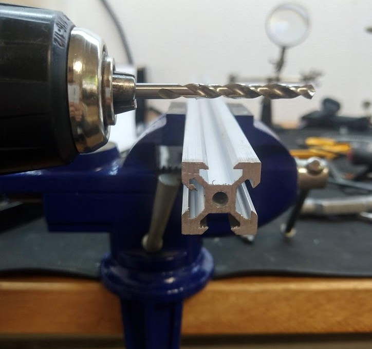
-
Drill holes into the corresponding places with a drill press. Use a 6 mm drill bit. The exact position of these holes is not crucial, they are only needed to let a screwdriver through.
-
Optional: before tapping the threads, countersink the hole with a multiple cutting edges countersink. This process will help you with the screw thread tapping.
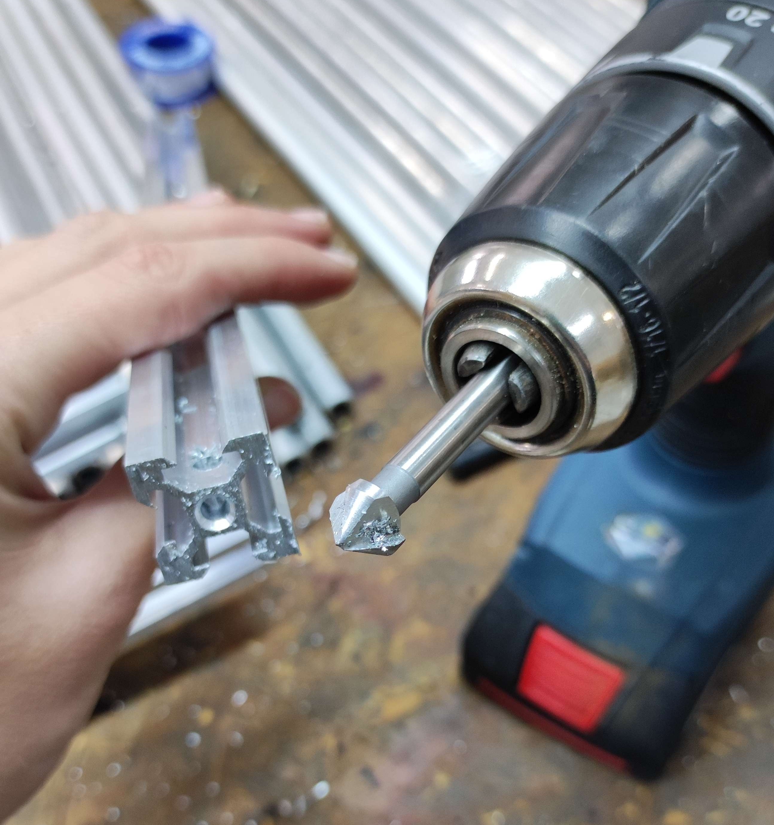
Tip
If you have drill bits of intermediate sizes (e.g. 4.2 mm for an M5 thread) using them before will make tapping much easier.
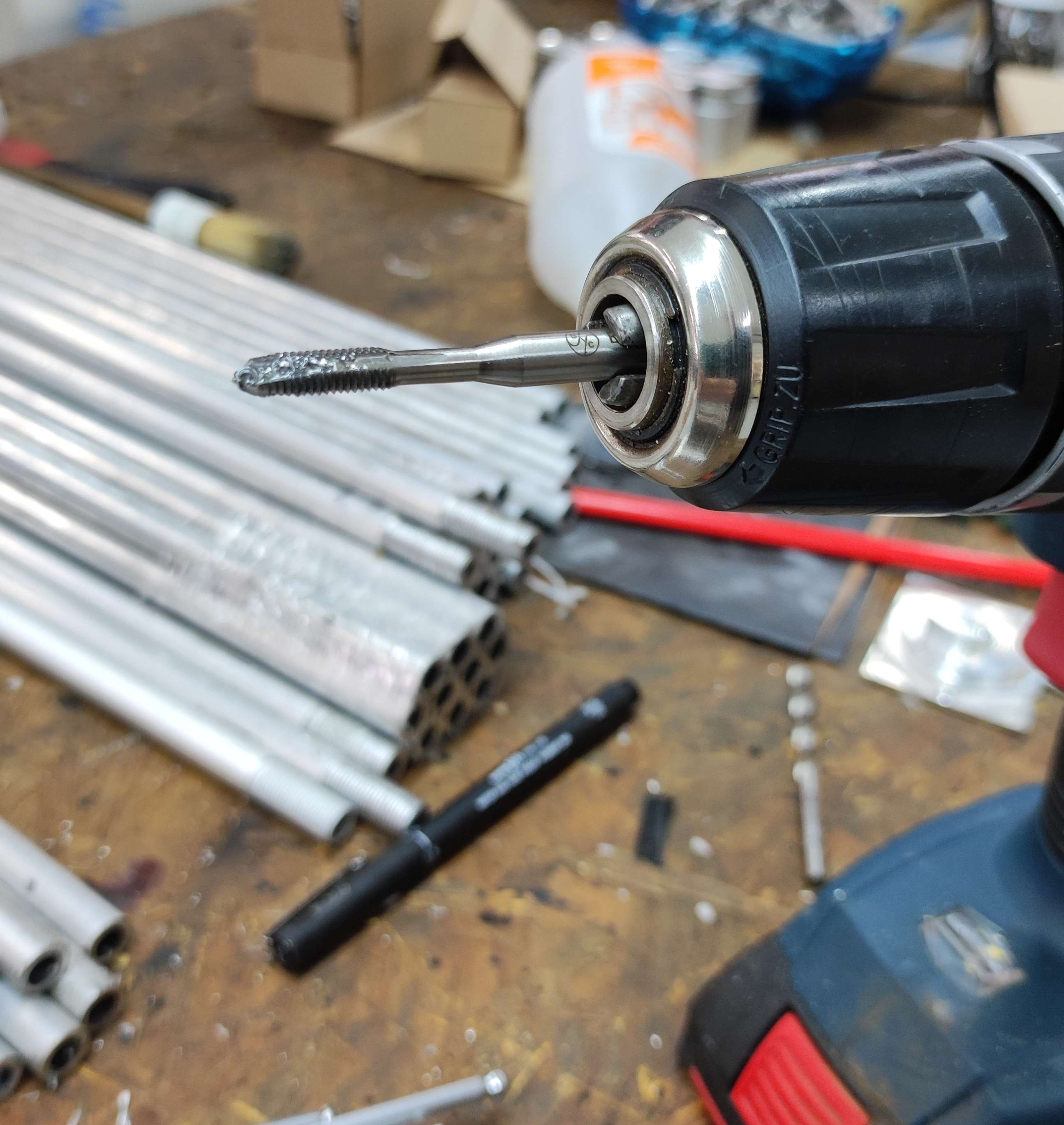
- Oil the tap, and introduce it axially into the pilot hole. Tap the thread with a back and forth pattern, until you reach the required length. Then reverse the rotation direction and gently remove the tap.
Tip
Don't forget to add lubricant and/or coolant. Threading taps are easy to break, and very hard to remove afterwards (potentially making the part unusable).
- Finally, remove any remaining burr with a file.
Note
We have explored three ways of cutting these profiles to length.
- The profiles in the commercial kit are cut on a CNC mill. This is the most precise and complex method.
- Our manual cuts turned out much better with a miter saw. Have a look at it's knowledgebase entry to learn how we did it. Instructions below this method.
- We also tried an automatic band-saw, more information can be found here. We set it to a low speed for cleaner cuts, but they still turned out a bit rough. Use the band-saw with the correct band (there are different bands for each material).
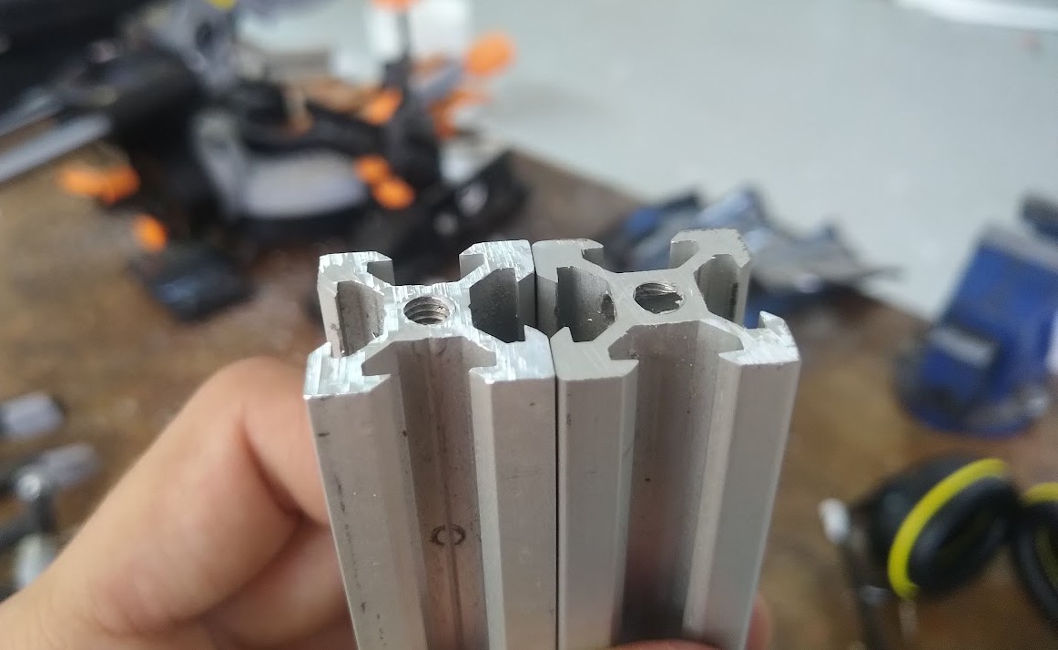
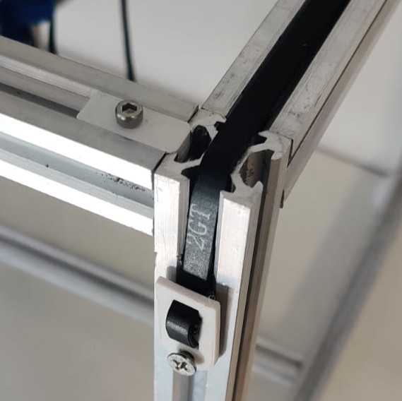
Tip
To make profile joints, we drilled holes and tapped threads into the aluminum profiles. This is sometimes called a "blind joint". See: https://youtu.be/2dvbn0rWA60?si=I2rkXLVrfva86K34
If doing this, we recommend finding a profile supplier that will cut the profiles for you. The DIY way with an angle grinder results in rougher edges, and even more delicate tools will not produce truly square edges. To avoid all of these issues you can buy a few hidden corner connectors (AKA inner steel brackets) o External angle connector, and skip all of that profile surgery. See also the warning about "bent" profiles further down this page.
It is a time vs. funds decision.
Step 3: Assemble the structure
Assembly instructions are available at the stepwise guide.
Tip
While building the frame, you can use a spirit level and a carpenter's square to make sure that the structure is stable and that all the profiles are aligned.
Warning
Some profiles will not ever make a perfect square when joined, even with perfect cuts. We found that some profiles are bent, that is, they present a small curvature that shows up when assembling the structure.
To mitigate this issue, you can try rotating the profiles about their axes, and then trying again. A flat reference can come in handy to find the direction of the bend.
Step 4: Alignment
To align the structure, first loosen a screw on the longer bottom side profile, leaving the other one tightened. You will otherwise probably have a harder time squaring the structure.
Use a square to iteratively align the top-side profiles to both of the sides. You will likely be following this procedure: loosen the screws and tighten them again in the correct position.
- Measure angle between two profiles with the square.
- Loosen screw that binds them. A slightly tightened screw might be better for small adjustments.
- Adjust the position and angle of the threaded profile, using the other one as your reference. Their sides should end up flush.
- Tighten the screw again, being very careful not to disturb your adjustment.
- Repeat 1-4 until the pair of profiles is square.
- Proceed to the next joint, leaving the bottom-side profile for last.
Tip
You can also gently tap the profiles with a rubber hammer or other soft-faced hammer (or thing) without loosening them completely. Tap the profiles until they reach the correct position, but be careful not to damage them.
Tip
If you have short profiles or other "flat" objects around, use them to also align the sides to total flushness while tightening the screw.
Use a spirit level to check for alignment.
- Measure the level of the long bottom-side profile. This should read zero if your table is level too.
- Measure the level of the long top-side profiles, and compare with the previous reading.
- Make adjustments, and check that the profiles are still square.
- Repeat 1-3 until the structure is level, and then check the sides for level too.
Tip
Spend some time going mad about this, you'll otherwise be doing it wrong (?).
Info
You will probably never see true level, but you can get close enough. Small deviations can be corrected through software (ref1, ref2) later on.
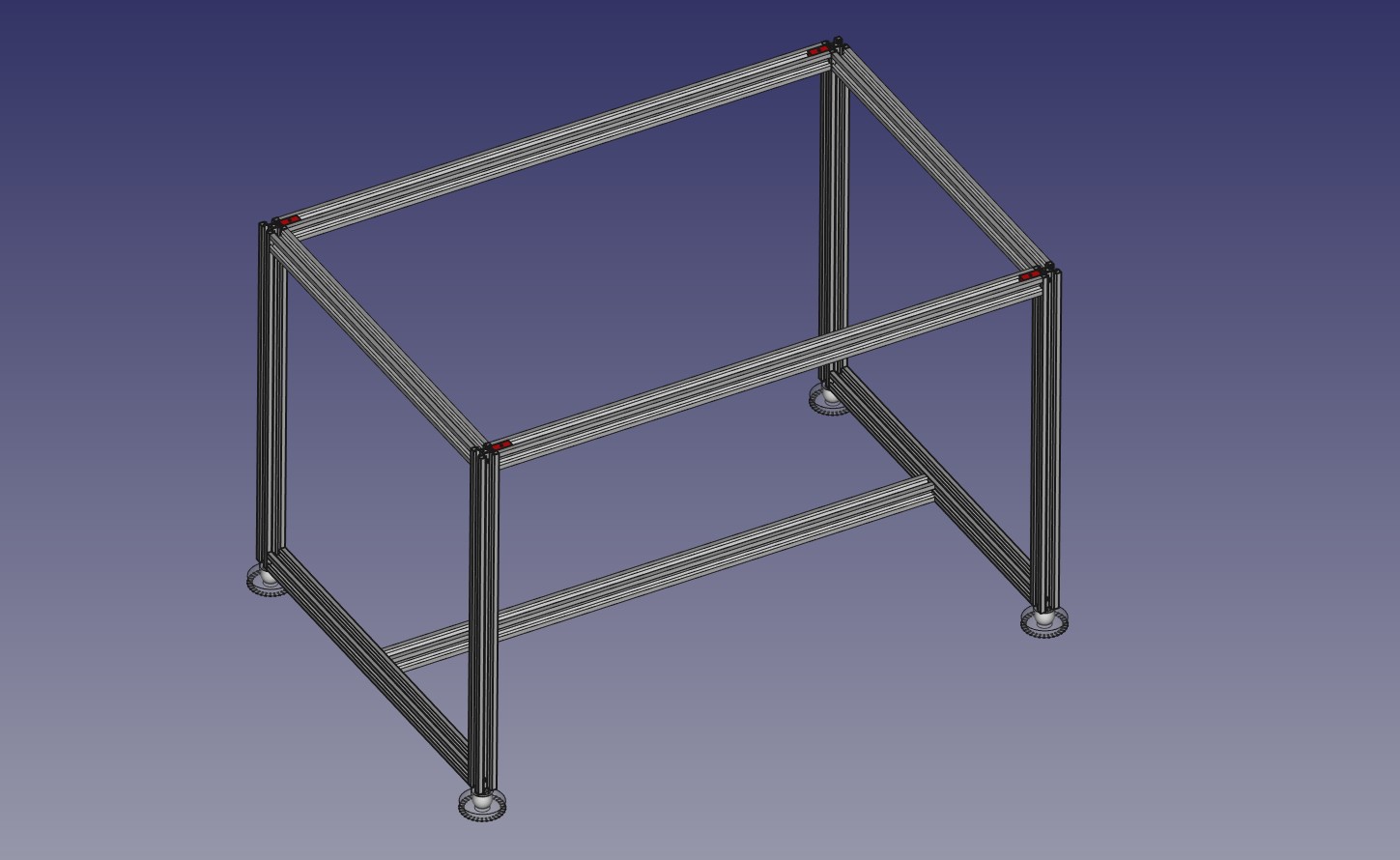
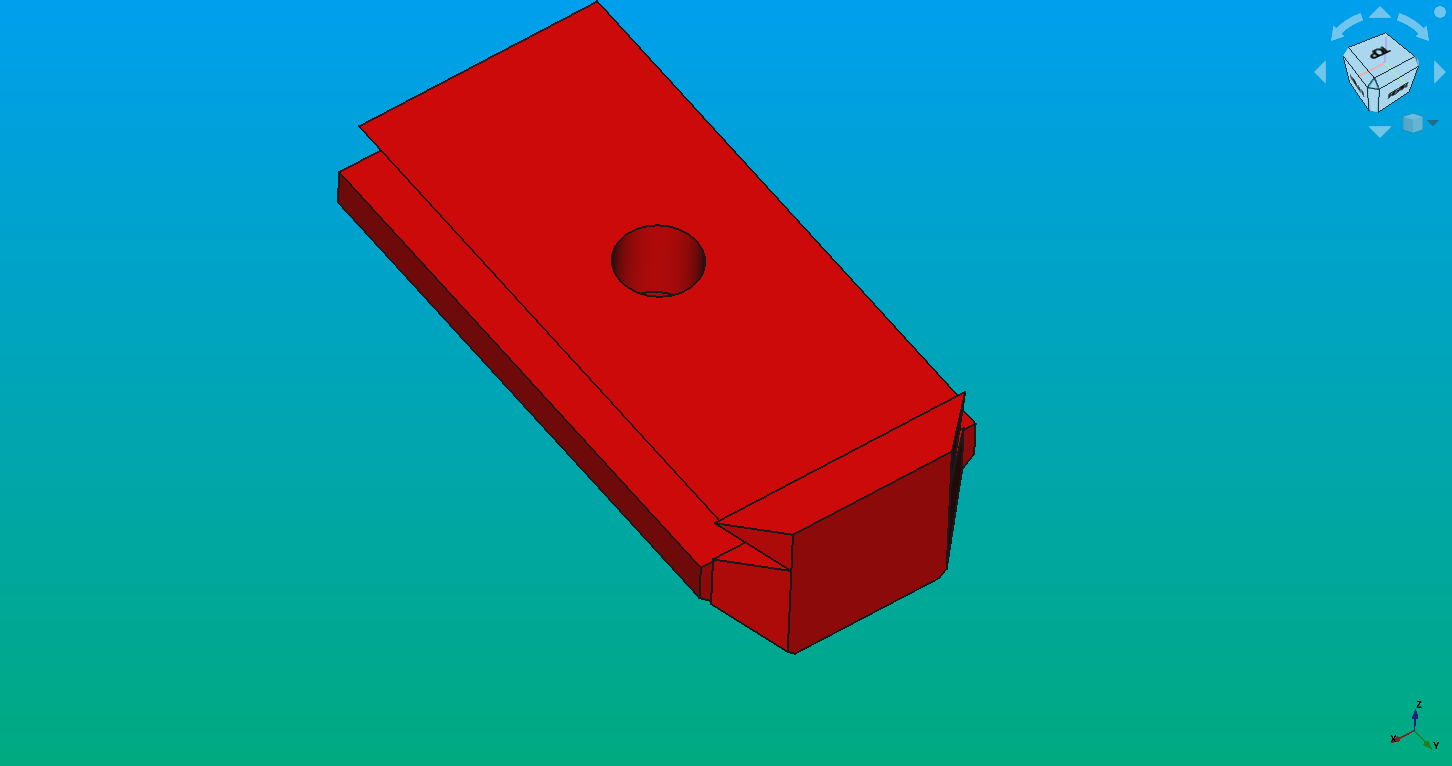
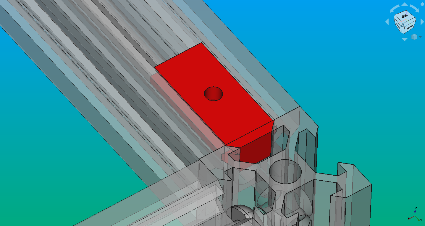
Twist locks
You might notice that the 600 mm profiles can rotate. To prevent this, we came up with the idea of using plastic locks (red piece). The locks have a small tab that fits into a slot on the profiles. This prevents the profiles from rotating. These locks are 3D printed, so they may require a slight amount of pressure to fit, which should not be an issue.
This video will help explain the issue: https://youtu.be/Z49ZmaI9Sb0
Video Walkthrough
Warning
The video is outdated, but still useful to understand the instructions below.
Assembly video walkthrough: https://youtu.be/ORg6Rlcb4A0
Interactions
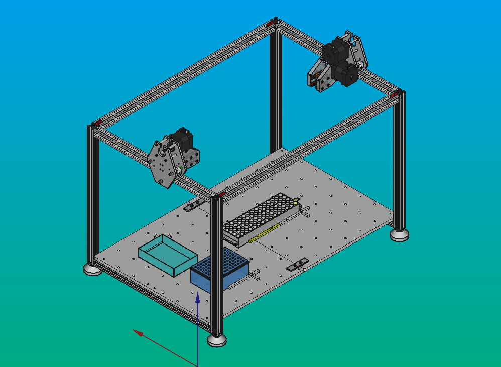
The structural frame is the backbone of Pipettin, holding everything together. It's like the robot's skeleton, supporting key parts like the XY carriages, baseplate, and electronics, so it interacts with most parts of the robot.
The baseplate will be located on the lower part of the structure, and objects will be placed on top.
The XY carriages will be located on the top of the structure.
The structure has the back-panel. It's located at the back, on the external face of the structure, joined by sliding screws and nuts, adding stability to the structure.
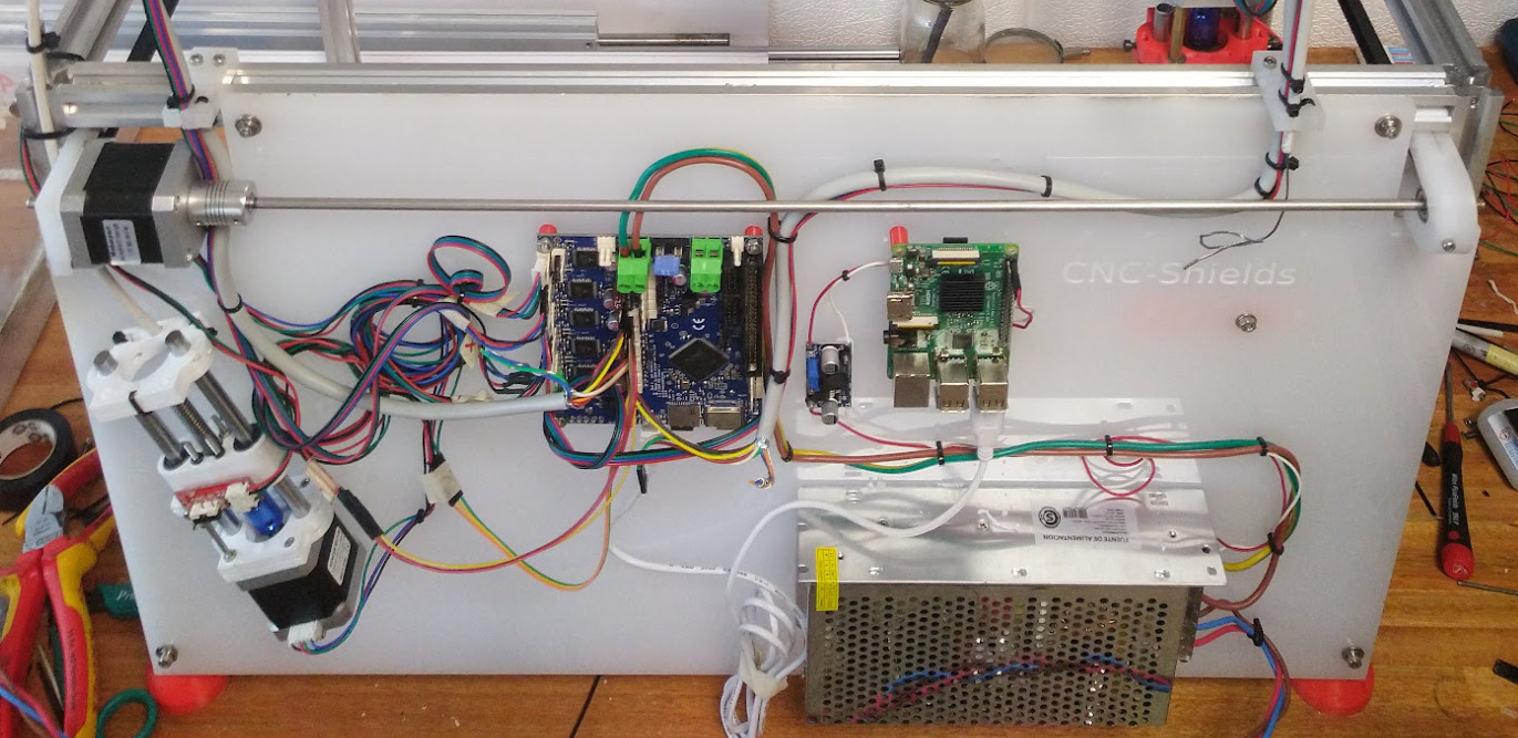
The electronics and the tool-changer motor, are mounted on its external face. The tool-parking posts and the tip-ejector post are mounted on the internal face.
Maintenance
Use a clean napkin or rag to remove dust or dirt from the structure, for the proper functioning of the moving parts. You should also check, with a spirit level and a square, that the structure alignment is correct.
The screws for the blind joints may loosen up over time. Use a screwdriver or allen wrench to check, make adjustments, and verify alignment with a square. Finally, run a simple test using the "Go to" button on the UI, to check that workspace alignment has not degraded.
Tip
When you are sure that everything is in place, you can try using "loctite" glue to, well, permanently lock the screws in place tightly.
Articulated legs may be replaced when damaged.
Design
We decided to use 20x20 V-slot aluminum profiles to do the structural frame because they are easy to machine and cheaper than other alternatives (i.e. rods), are lightweight, and available in most parts of thw world. Suitable structures can also be made out of pipes and 3D-printed parts (e.g. like the MPCNC).
We used M5 button screws to assemble the profiles, as explained in Assembly Steps, and created our own accessories such as lockers and articulated legs since it was cheaper than using profiles accessories, like hammer, nuts and squares.
Models
The latest versions of all files are available at GitLab: https://gitlab.com/open-la/pipettin-bot/-/tree/master/models/MK3/structure
Development
These 3D-printed parts were designed in FreeCAD 1.0, and saved in the native FCStd format. Printable STL files were printed on an Original Prusa i3 MK3.
To learn more about these file formats visit here.