Z Axis Linear Actuator
Z Axis Linear Actuator
Info
Discord forum thread: Motion System License: CERN-OHL-S-2.0
Overview
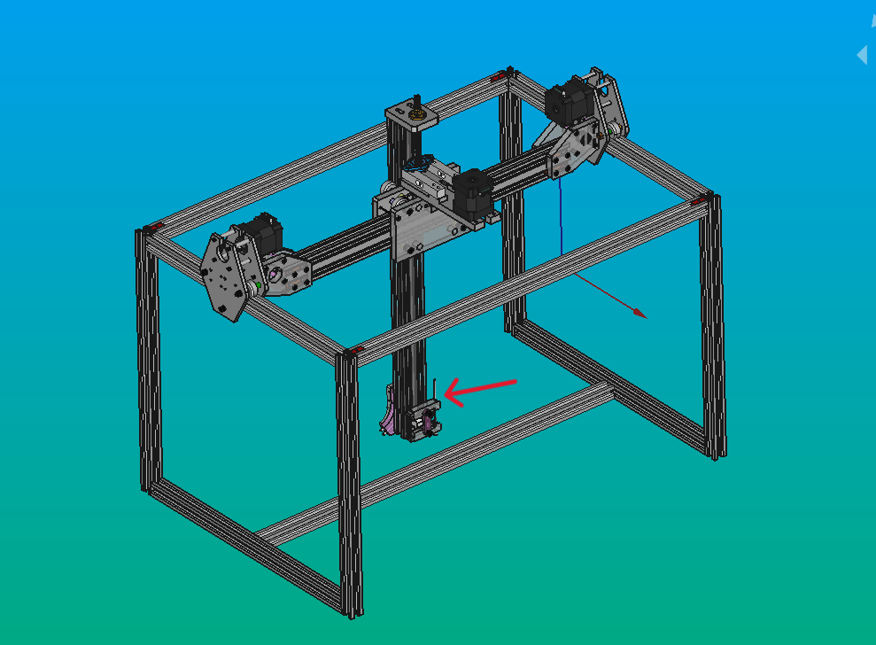
The Z-axis linear actuator connects the machine's structural frame to the tools (micropipettes and other equipment), giving them the ability to move. It consists of a movement system that transmits motion using a threaded bar and a pulley system to change the direction of force, generating a vertical profile movement when the tool is placed.
Throughout this section you will find general guidelines for building the Pipettin bot's Z-axis actuator, such as their drawings, manufacturing instructions and other options you could consider for your Pipettin bot.
Usage
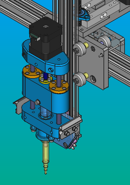
The motion system is composed of a motor, a pulley, a belt, and a threaded bar. The motor drives the pulley, which in turn drives the belt. The belt moves the second pulley, which transmits force to the threaded bar. The threaded bar moves the profile.
The motion system uses a 20x40 V profile as a linear rail. However, it can also be used with a 20x20 V profile. If you use a 20x20 V profile, you will need to adjust the 3D models to match the dimensions of this last one.
The lower section is connected to the Micropipette and to the Tool-changer through the Tool-changer Key, with a designated hole in the Z-profile for the insertion of the Tool-changer. Meanwhile, at the upper end, the system will be securely fastened to the X-axis using two plates and multiple screws.
Furthermore, you must determine the vertical gap between the workbench (Baseplate surface) and the maximum reachable height for cutting the 20x40 V profile. You can ascertain this measurement by employing the complete motion system, the profiles, and the tool dimensions. Alternatively, you can calculate the distance and make adjustments through programming.
WIP
Do not move nor touch the linear actuator while the robot its working or it can cause an injury to the user or damage the robot.
Assembly
The Pipettin Bot's Z-axis linear actuator is assembled inside the XY-axes. Therefore, building the XY Linear Actuator is the previously step in the Motion System Assembly process.
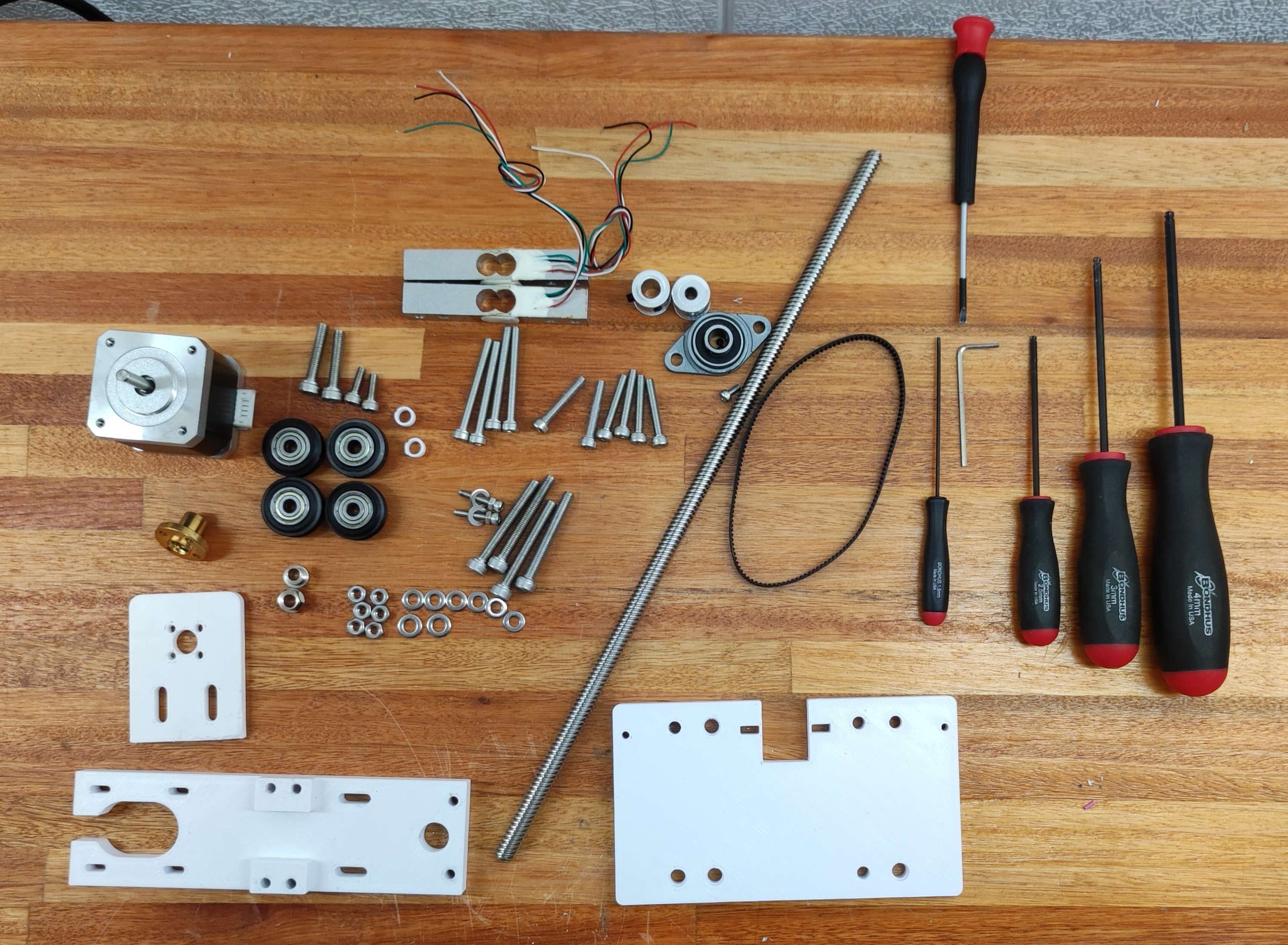
Step 1: Gather parts
Parts and materials:
3D printed parts:
- 1x CARB-XZ-ST.V3
- 1x CARB-XZ-ST-PROFILE.V1
- 1x CARB-XZ-PL.V4
- 4x SEP-5-10.2.V1
Off-the-shelf parts:
- 2x M5 screws x 45 mm
- 4x M5 screws x 35 mm
- 2x M5 eccentric nuts
- 4x M5 nuts
- 1x THSL Ø8 8x4 threaded rod
- 1x Pulley GT2 for THSL threaded rod
- 1x Pulley GT2 for NEMA17 stepper motor
- 1x Closed GT2 belt 280 mm
- 1x KFL08
- 2x M4 screws x 20 mm
- 4x M4 screws x 30 mm
- 4x M4 screws x 40 mm
- 4x M4 square nuts
- 8x M4 Washers
- 2x Load Cell Weight Sensor HX711
- 1x M3 screw x 5 mm
- T8 Flange Lead Screw Nut Ø8 8x4
- 1x NEMA17 Stepper Motor
- 4x M2 screws
- 4x V-wheels 11 x Ø24
- 1x 20x40 V aluminum profile
Tools for assembly:
-
Hex Wrench screw drivers:
- 4 mm
- 3 mm
- 2.5 mm
- 2 mm
- 1.5 mm
Step 2: Manual Machining Instructions
Parts and materials:
- Aluminum 20 x 20 V profiles.
- PLA filament: 200 g
Tools:
- Manual drill
- M5 and M3 screw tap
- Band-Saw
- Band: 20 x 2362 x 8/12d
- File
- Drill Press
- Cooling lubricant
- 3D printer
Instructions
-
First, you must print the 3D parts. The files are here. Do the adjustments that you need to do in case of using other type of profiles.
-
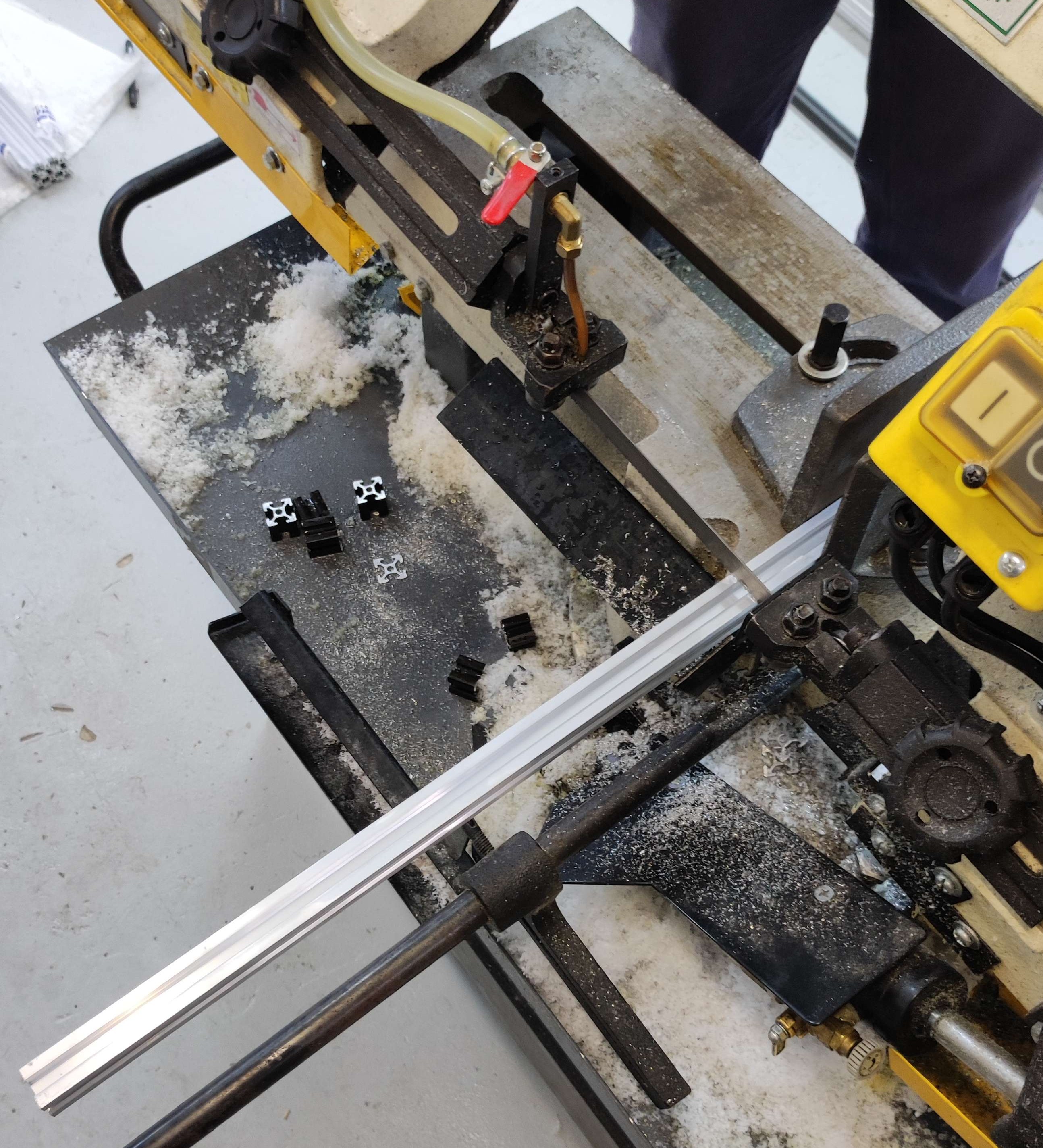
Once you have all the parts, you need to measure the dimensions of the structure, specially the height, to cut the 20x40 V profile with the Band-Saw.
This height will be, at most, from the upper surface of the base to the lower surface of the X-axis profile. This measurement could be fully determined once you have assembled the tool-changer and the tool dimensions. Likewise, any movement can be corrected through programming. It is better to have a larger profile than a shorter one.
- Then, do the internal profile threads using an M5 screw tap. You only have to do it on one side of the profile. To do so, first you have to countersink the hole with a multiple cutting edges countersink. This process will help you with the screw thread tapping.
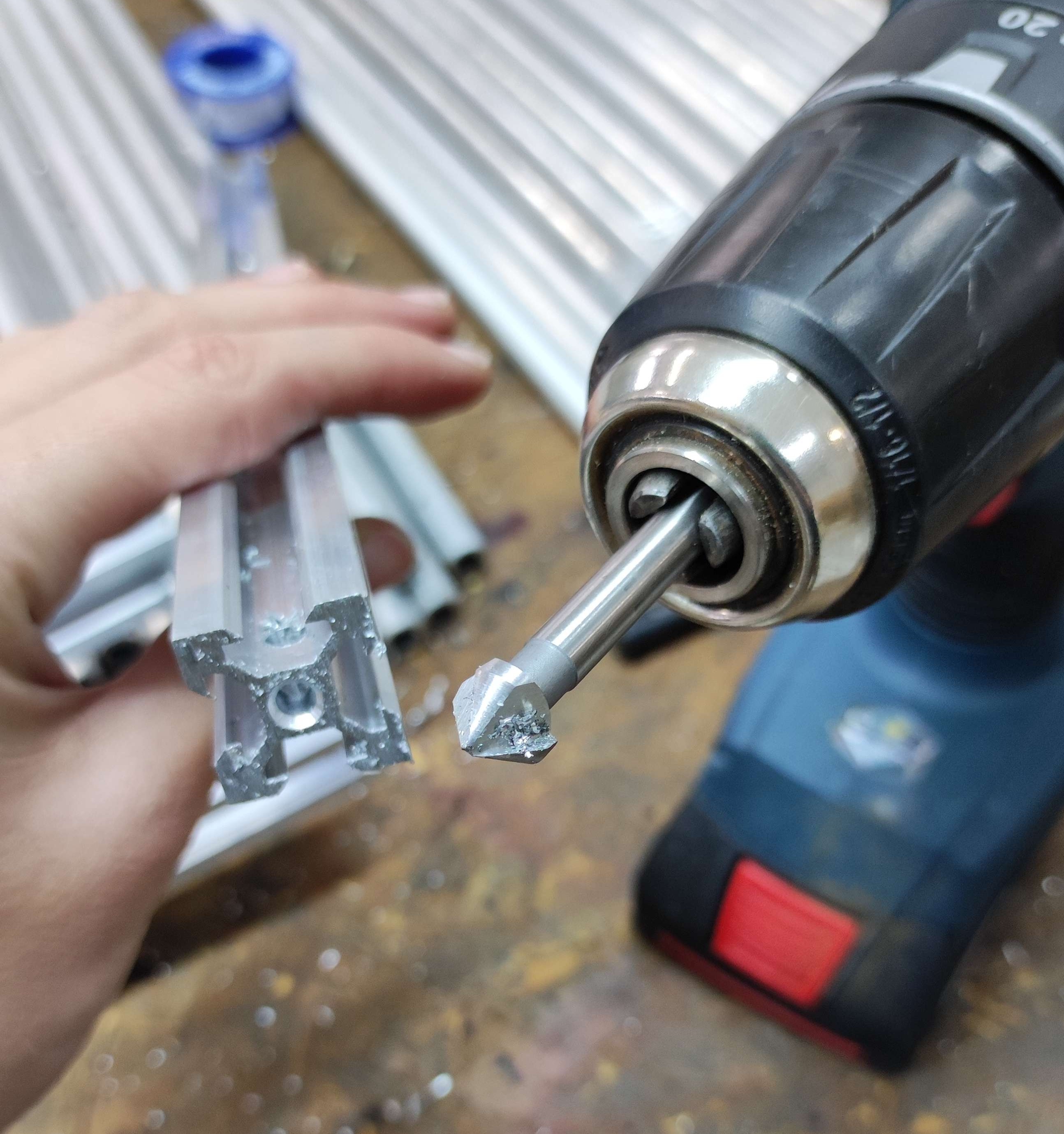
- Then, introduce the screw tap axially into the pilot hole, and then reverse the rotation direction to complete the process. Don't forget to use cooling lubricant.
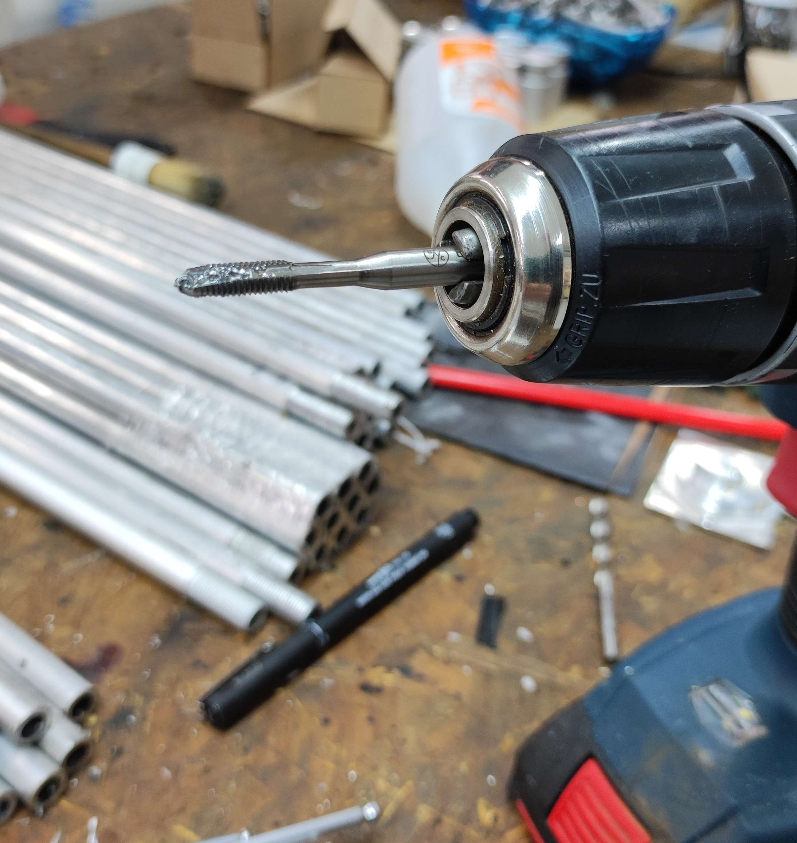
-
Finally, remove burr with a file.
-
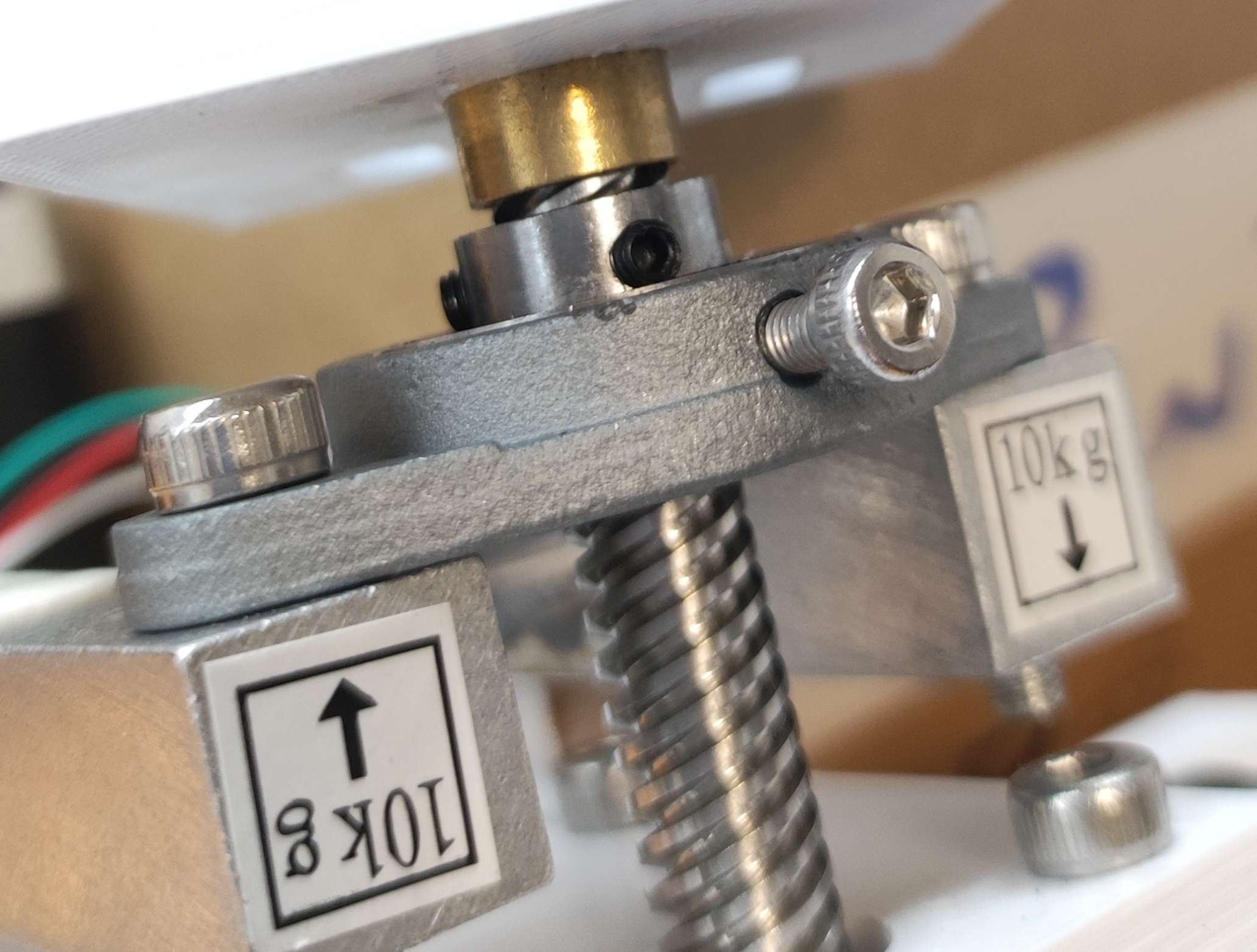
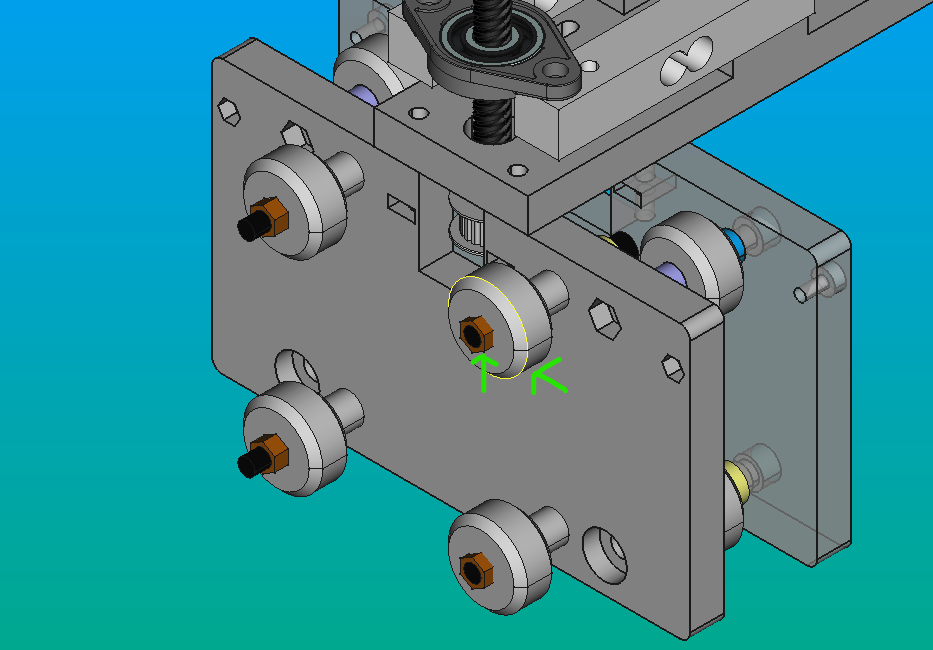
Optional step: drill a hole in the KFL08 and tighten a screw (as shown in the image) in order to eliminate any vertical play in the pillow block bearing.
Step 3: Assemble the actuator
-
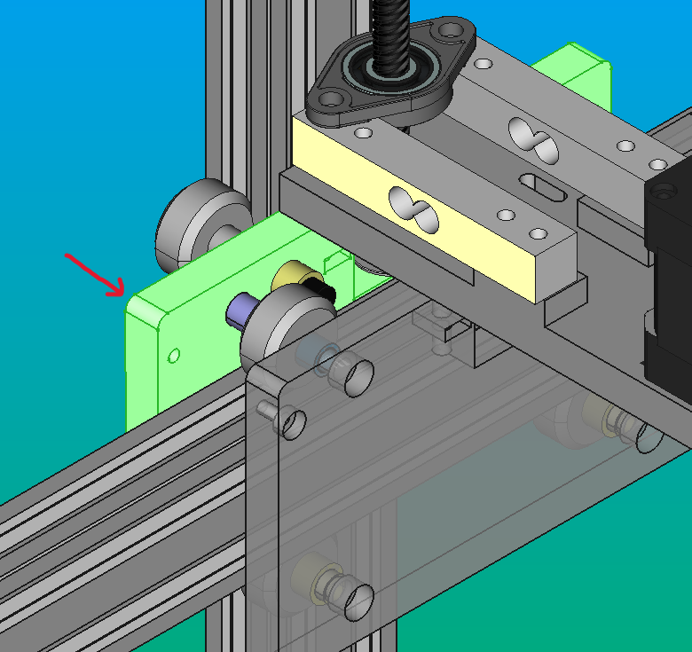
Before placing both X-axis plates (CARB-XZ-PL and CARB-XX-PL.V1) XY-axis assembly, you need to insert four M5 screws (2 x 45 mm and 2 x 35 mm):
-
The longer ones go into the holes where you will also place the eccentric nut.
- The shorter ones go into the remaining two holes.
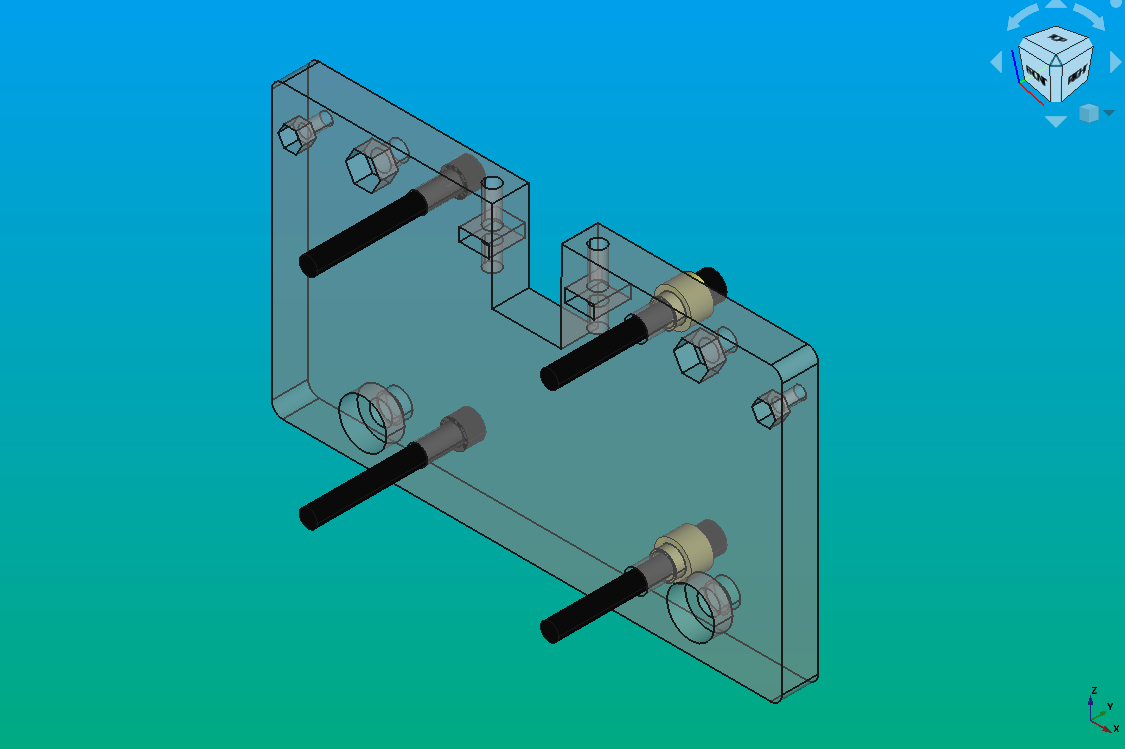
To simplify the assemble, we recommend adding nuts to all the screws to prevent them from slipping.
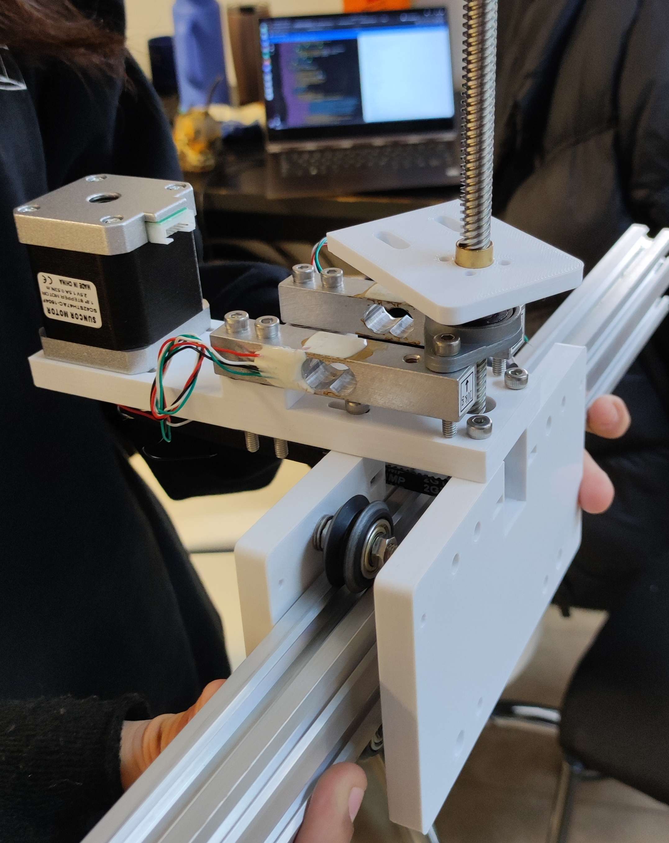
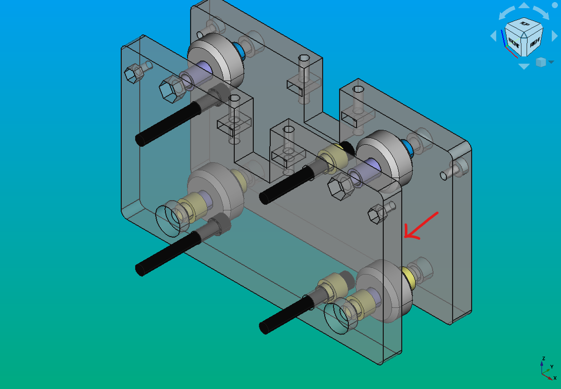
- Before attaching the motor plate to the X-axis base, place the threaded rod with the threaded rod pulley. Also, install the belt (it's not shown in the image, you can watch the video at the end).
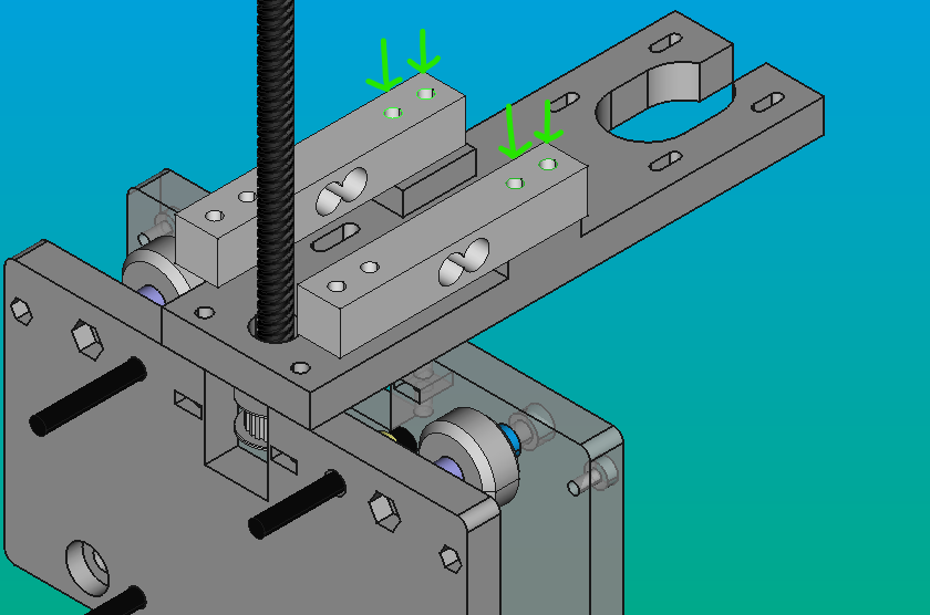
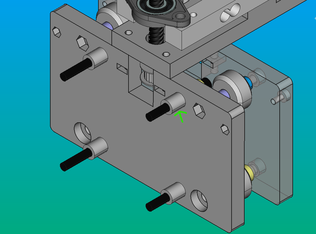
- Attach the motor plate (CARB-XZ-ST) to the X-axis plates (CARB-XZ-PL and CARB-XX-PL.V1) using four M4 screws x 30 mm and four M4 square nuts. Holes in green:

- Mount the load cells using 4 M4 screws x 40 mm. Add M4 washers to provide greater flexibility to them.
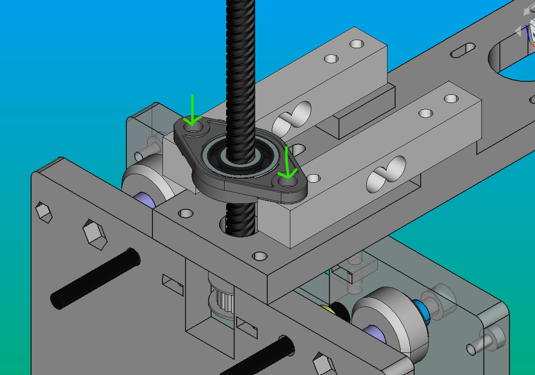
- Position the KFL08 pulley above the load cells and screw it onto these cells with 2 M4 screws x 20 mm.
-
Afterward, install the motor (using 4 M2 screws) and its corresponding pulley, and thread the belt through. Adjust the motor until the belt is taut.
-
Fit the separators, the wheels and their respective nuts.
-
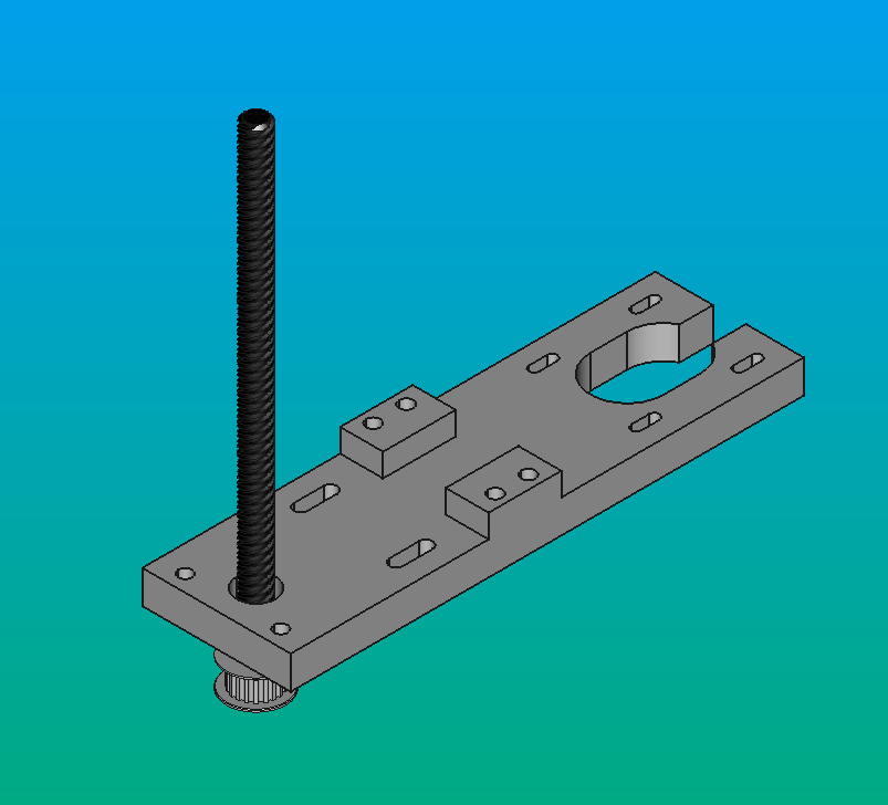
Fit the T8 Flange Lead Screw Nut on the CARB-XZ-ST-PROFILE.V1 and then put the T8 lead screw through it
-
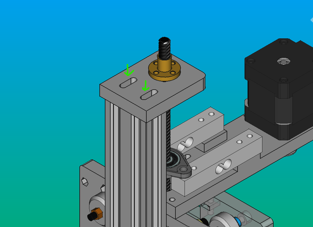
Thread the 20x40 profile with threaded ends through the wheels and screw it onto the upper plate using two M5 screws x 45 mm.
Assembly video
Interactions
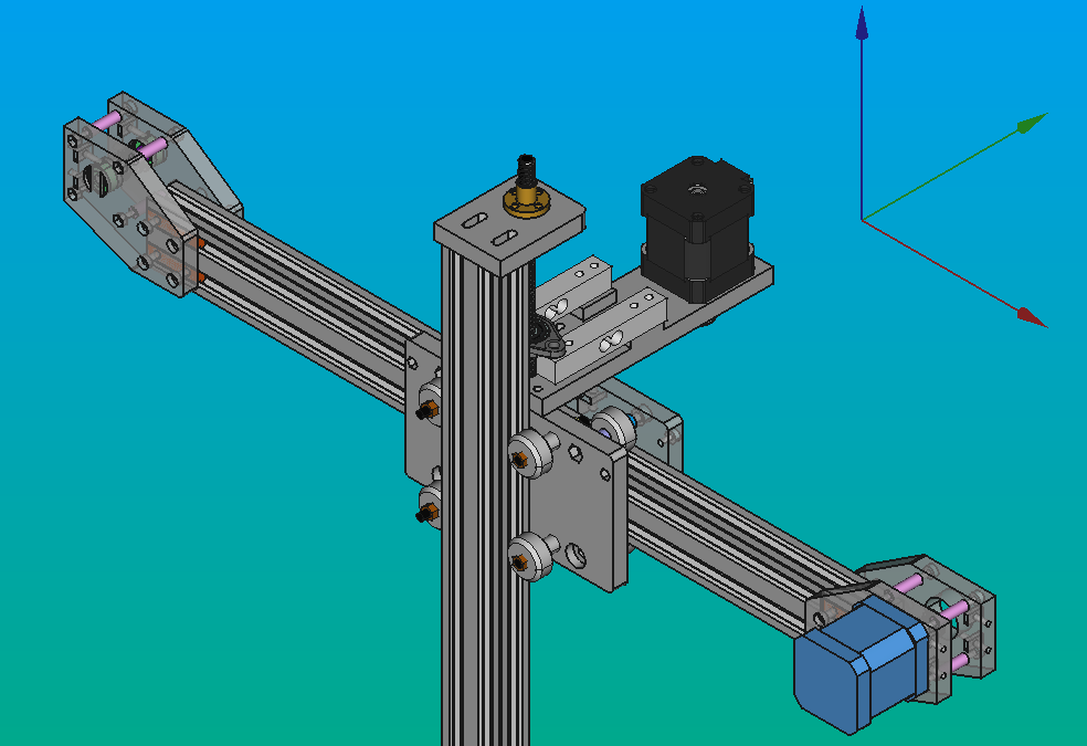
As mentioned before, the Z-axis of the Motion System is a fundamental part of Pipettin bot. It interacts with the XY-Axes Linear Actuator, the Electronic Micropipettes and the Tool-changer.
The Z-axis Linear Actuator will be located on the X-Axis profile. Both are connected through this plate (CARB-XZ-PL).
The tools (in our case a micropipette) will be located on the bottom of the Z-axis profile. And the Tool-changer will be located on the other face of the Z-axis profile.
The Toolchanger will be at the lower end of the profile, attached with some nuts and screws. It's going to have the micropipette attached to him. In case you don't have the toolchanger working, your tools can be attached to the profile with nuts and screws instead of to the toolchanger.
Design
The design of this system must consider the movement of the X and Z-axes so that they can achieve their expected performance without interfering with each other. If you want to modify or create a new version of the actuator, you must have in mind the following:
-
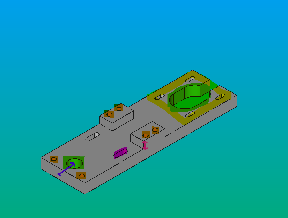
For the design of the 'CARB-XZ-ST.V3' plate:
-
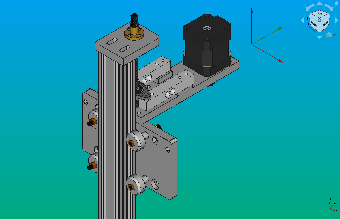
The length of the belt: This will determine the length of the plate. A smaller plate will be more balanced and will provide a greater range of motion to the actuator. Additionally, the motor can be adjusted to provide the necessary tension to the belt. On the image, in green.
- The load-cells dimensions and their position. On the image, in orange.
- The proximity of the 20x40 V profile respect to the threaded rod, so that the KFL08 has space and can be added to the load cells. On the image, distance in blue.
- The dimensions of the motor. On the image, in yellow.
To incorporate all the off-the shelf parts mentioned, each hole needs to be in the correct place not to interfere between them, and the dimensions of the screw heads must be taken into account (on the image, holes an distance in pink).
-
For the design of the 'CARB-XZ-ST-PROFILE.V1' plate:
-
The distance between the profile and the threaded rod.
-
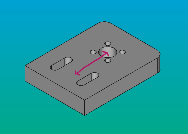
For the design of the 'CARB-XZ-PL' plate:
-
The position of the profile and the distance that should be between the axes of the wheels. On image, distances in pink and green.
- The position of the axes required to place the X-axis behind the plate. On image, distance in green.
- Some screws and nuts needed to be countersunk not to affect the movement of the axis. Example in yellow.

It's important to consider that with larger plate dimensions, you will obtain a smaller range of movement. Therefore, optimizing space is crucial. Currently, we are working on a new version of these actuators to increase the range of movement.
We decided to have the parts printed because they are a cost-effective and accessible resource.
We opted for a 20x40 profile for the vertical axis since it offers greater stability compared to a template rod, as the previous version of Pipettin bot had.
We used eccentric nuts to adjust the tension between the wheels and the axis.
Models
The latest versions of all files will be available at this link
-
Profiles: custom part
- Material: Aluminum 20x40 V-Slot
- CAD: 2040V-490.V1.FCStd
- Part number: 2040V-490
-
CARB-XZ-ST: custom part
- Material: PLA
- CAD: CARB-XZ-ST.FCStd
- Drawings: CARB-XZ-ST-280.V3_DRAWING.pdf
- Part number: CARB-XZ-ST
-
CARB-XZ-ST-PROFILE.V1: custom part
- Material: PLA
- CAD: CARB-XZ-ST-PROFILE.FCStd
- Drawings: CARB-XZ-ST-PROFILE.pdf
- Part number: CARB-XZ-ST-PROFILE
-
CARB-XZ-PL.V4: custom part
- Material: PLA
- CAD: CARB-XZ-PL.V4.FCStd
- Drawings: TO DO: still working on it
- Part number: CARB-XZ-PL
-
SEP-5-10.2.V1: custom part
-
M2 Screws and nuts: off-the-shelf parts.
- M5 Screws and nuts: off-the-shelf parts.
- M3 Screws and nuts: off-the-shelf parts.
- M4 Screws, washers and nuts: off-the-shelf parts.
- THSL Ø8 8x4 threaded rod: off-the-shelf parts.
- Pulleys GT2: off-the-shelf parts.
- GT2 belt 280 mm: off-the-shelf parts.
- KFL08: off-the-shelf parts.
- Load Cell Weight Sensor HX711: off-the-shelf parts.
- T8 Flange Lead Screw Nut Ø8 8x4: off-the-shelf parts.
- NEMA17 Stepper Motor: off-the-shelf parts.
- V-wheels 11 x Ø24: off-the-shelf parts.
Development
These 3D-printed parts were designed in FreeCAD 2.1 and 2.0, then exported in the FCStd format for slicing. They were printed on an Original Prusa i3 MK3 using STL files. Most pieces were inspired by Jubilee's designs for compatibility between these CNC machines tools.
To learn more about these file formats visit here.