XY Axes Linear Actuator
XY Axes Linear Actuator
Info
Discord forum thread: Motion System License: CERN-OHL-S-2.0
Overview
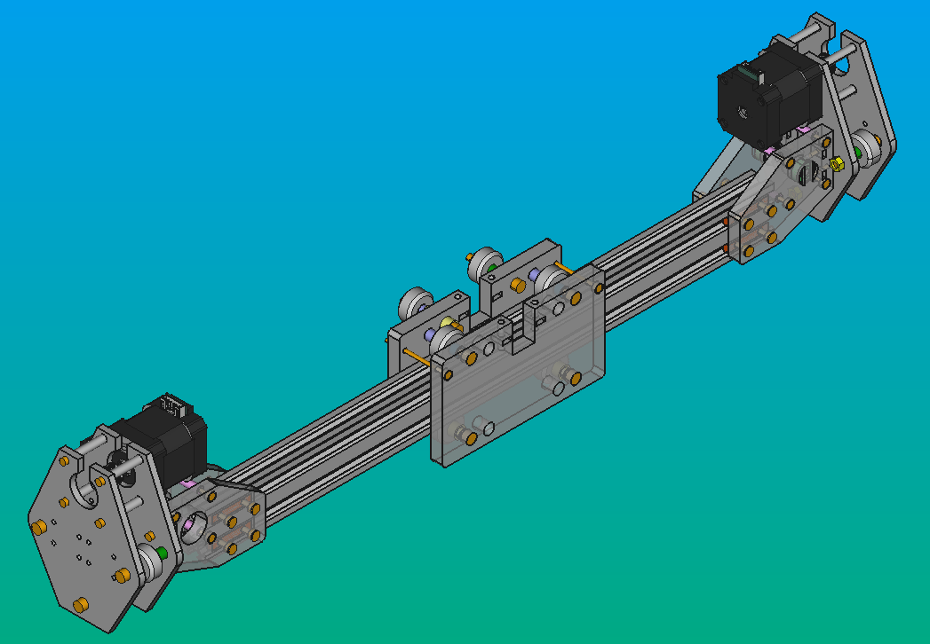
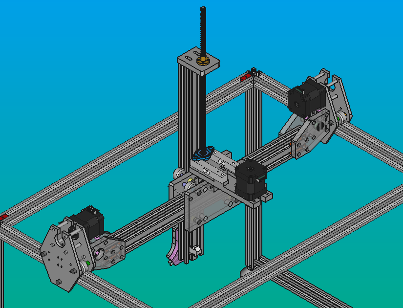
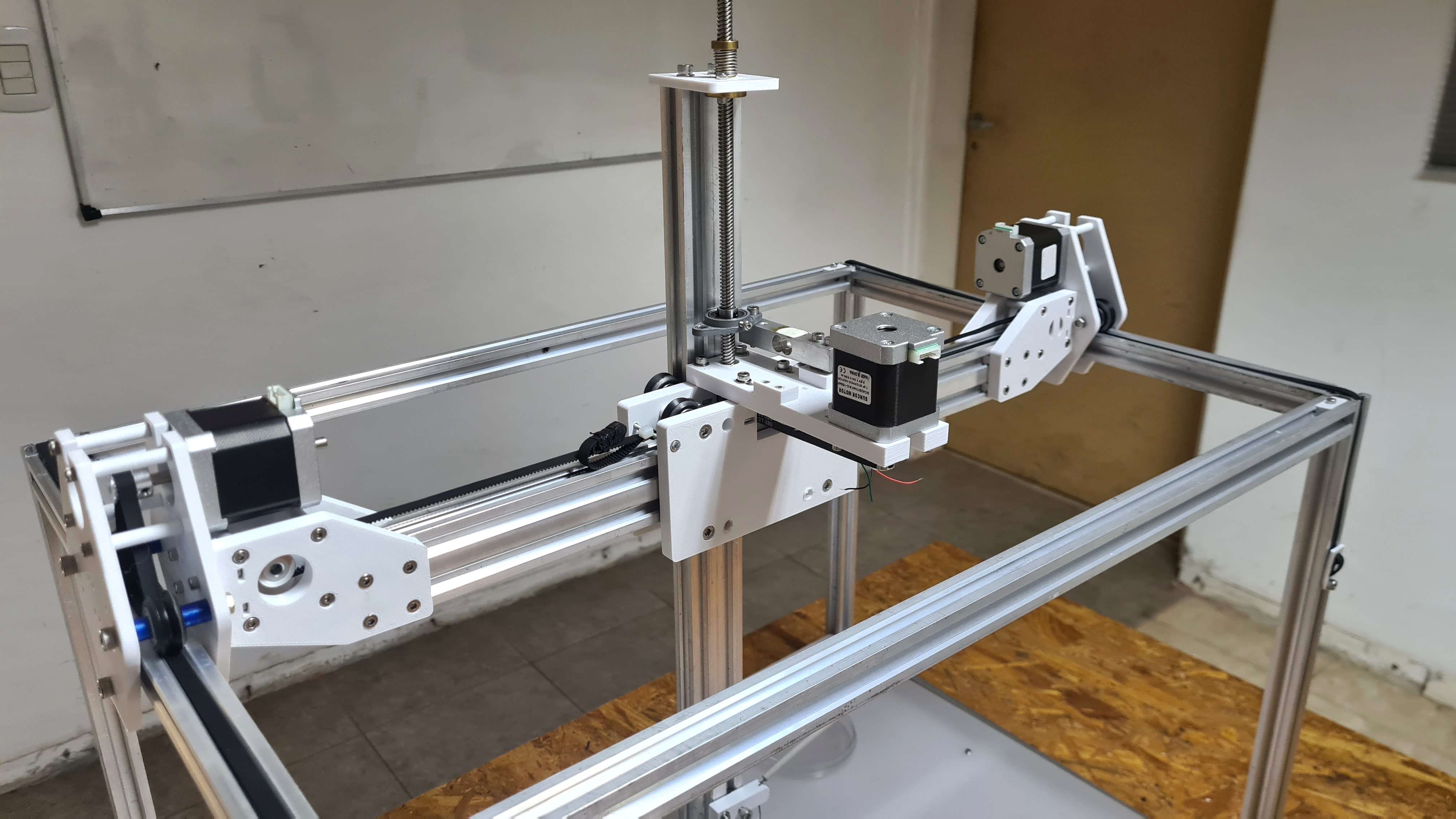
The X-axis linear actuator connects the Y-carriages with the Z-axis linear actuator and it is connected to the structure of Pipettin bot as well. It consist of a 20x40 aluminum V linear rail and a pulley system that moves a central carriage (X-carriage) connected to the Z-axis linear actuator.
Throughout this section you will find general guidelines for building the Pipettin bot's XY-axes actuator, such as their drawings, manufacturing instructions and other options you could consider for your Pipettin bot.
Design files are available here
Usage
You can assemble the XY-linear actuator without assembling any other part of the robot except the Z-Axis Linear Actuator and the Y-carriages. The assembly of this last one will be explained in this same section. Also, it is recommended to have the accurate measurements of the Structural Frame. However, we recommend following the steps outlined on the assembly guide.
The XY-linear actuator is connected to the rest of the robot through its joints with the Y-carriages. This, as well, connects the Z-linear actuator to the robot.
The system utilizes a 20x40 V linear rail, but it can also be adapted to a 20x20 rail (in which case, the 3D models will need to be adjusted accordingly).
Danger
Do not move/touch any linear actuator while the robot its working or it can cause an injury to the user, damage the robot, or cause decalibration of tools.
Assembly
The XY-linear actuator is assembled between the two Y-carriages of Pipettin bot. Before mounting it, you must have almost entirely completed the Z-axis linear actuator assembly process.
Step 1: Gather parts
Parts and materials:
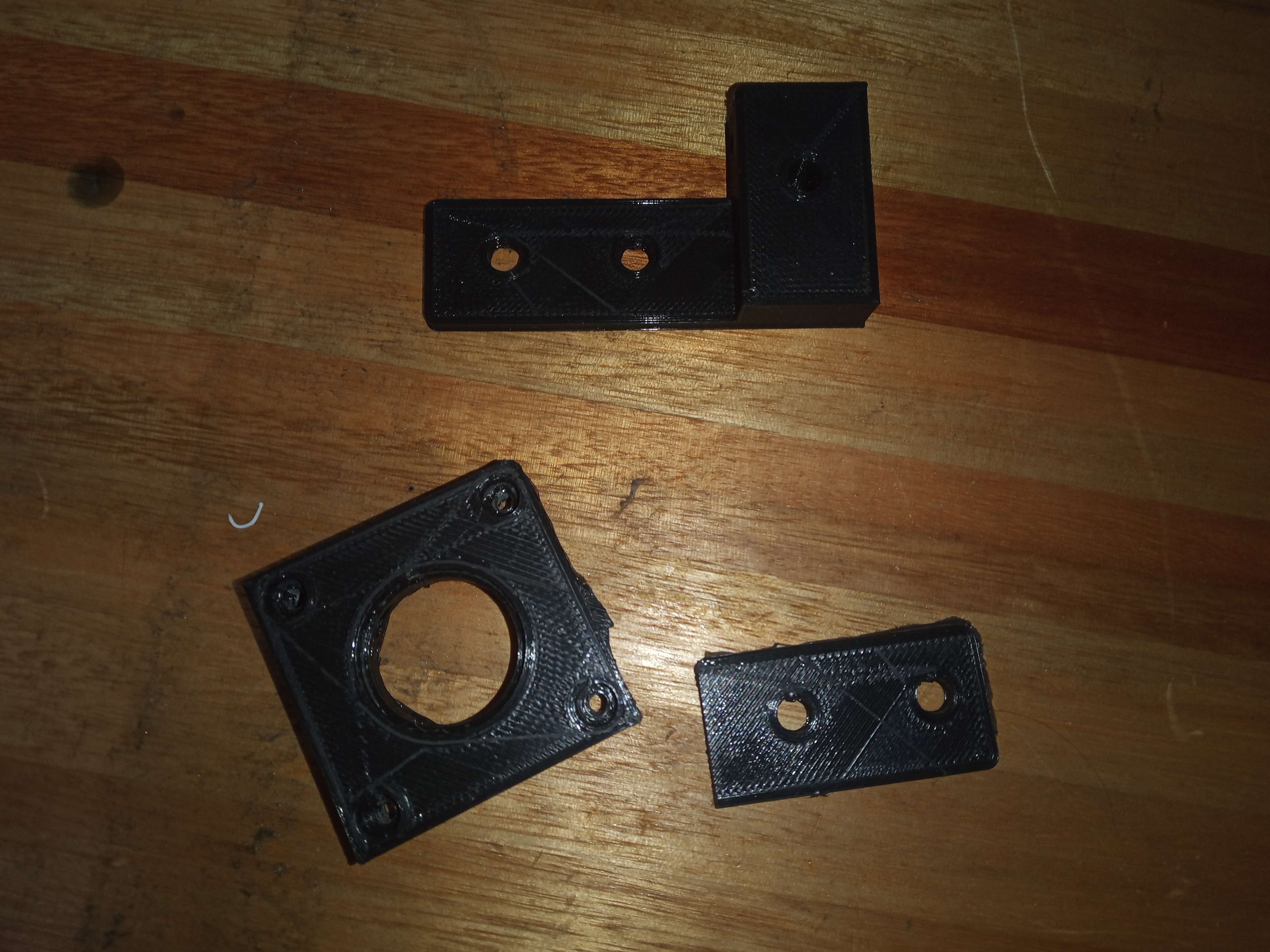
3D printed parts:
- 1x CARB-XY-PU1.V2
- 1x CARB-XY-PU2.V2
- 1x CARB-XY-ST1.V3
- 1x CARB-XY-ST2.V3
- 8x SEP-5-20.V1
- 1x SEP-5-8.1.V1
- 1x SEP-5-3.1.V1
- 1x SEP-5-7.8.V1
- 6x SEP-5-10.2V1
- 6x SEP-5-4.V1
- 2x SEP-5-5.8.V1
- 2x SEP-5-10.V1
- 8x SEP-4-27.4.V1
- 4x SEP-5-6.2.V1
- 1x CARB-XZ-PL.V1
- 1x CARB-XX-PL.V1
- 8x 2020_DOUB_TWLO_M4.V1
- x4 CARB-Y-PL.V1
Of-the-shelf parts:
- 16x M3 x 40 mm screws
- 16x M3 x 50 mm screws
- 8x M3 x 20 mm screws
- 14x M3 nuts
- 16x M4 x 12 mm screws
- 16x M4 nuts
- 14x M5 x 40 mm screws
- 14x M5 nuts
- 12x M5 eccentric nut
- 1x 2040V x 490 mm profile
- 3x Stepper motor
- 2x M5 Rolling-element bearing
- 4x GT2 16T pulleys
- 3x GT2 Timing Belt
- 1x 5mm x 16mm Axis bar.
- 14x V-wheels 11 x Ø24
Tools for assembly:
- Alen wrenches, sizes: M3, M4, M5.
- Hex screwdrivers or wrenches.
Step 2: Profile Manual Machining Instructions
Parts and materials:
- Aluminum 20 x 20 V profiles.
- PLA filament: 300 g
Tools:
- Manual drill
- M5 and M3 screw tap
- Band-Saw
- Band: 20 x 2362 x 8/12d
- File
- Drill Press
- Cooling lubricant
- 3D printer
Instructions
-
The first thing you have to do is print the 3D parts. Files are available here
-
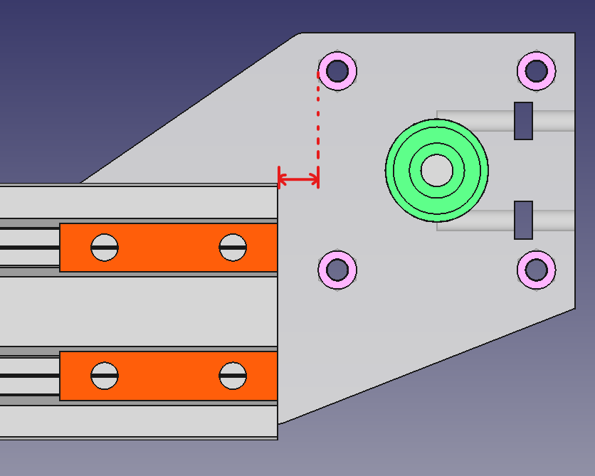
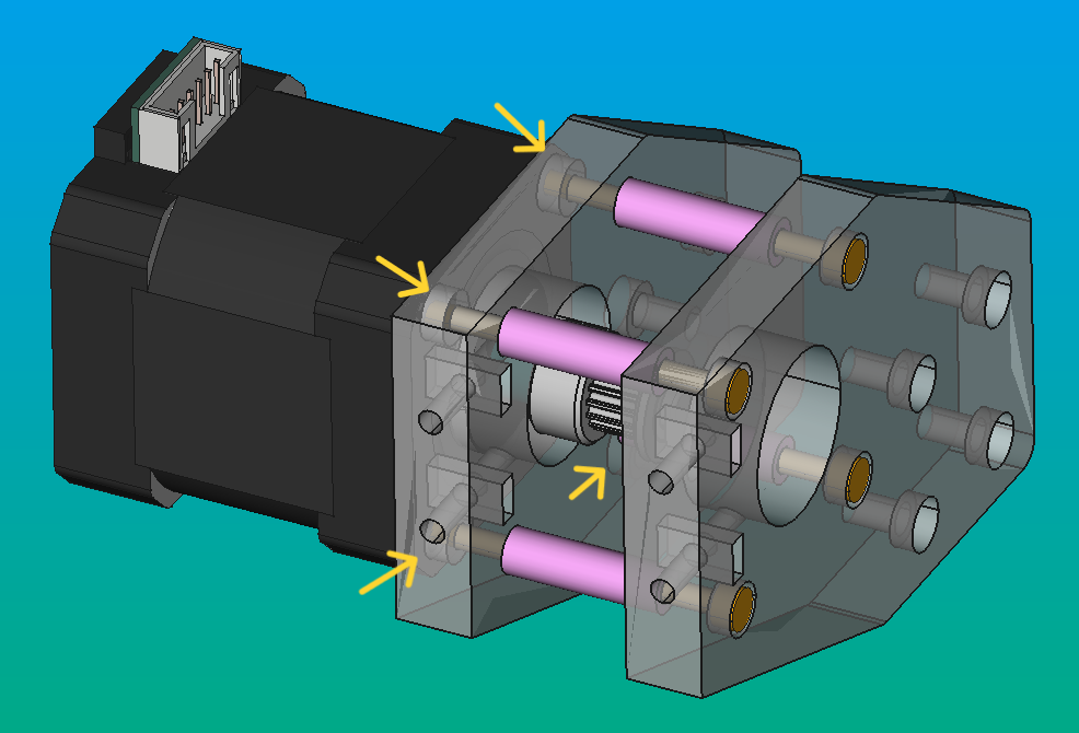
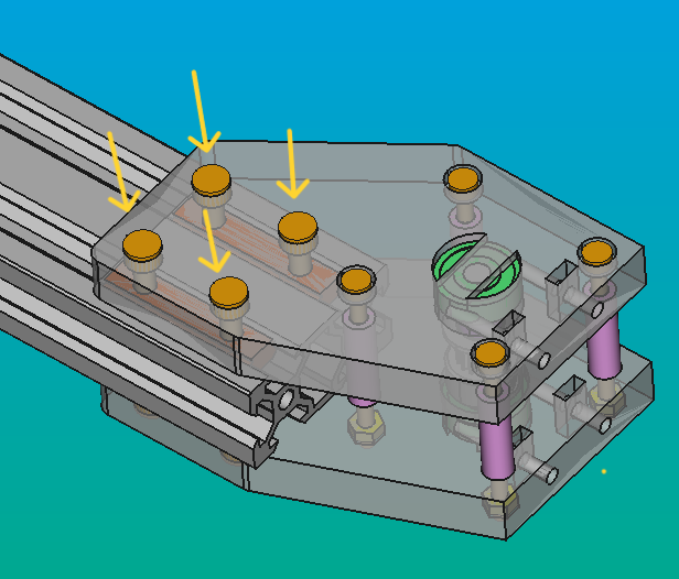
Measure the distance between the two Y-carriages. To do so, you must know that you need some space for the 3D printed parts with the SEP-5-20.V1 for stepper and pulleys. Then, you cut the 20x40 profile with the Band-Saw.
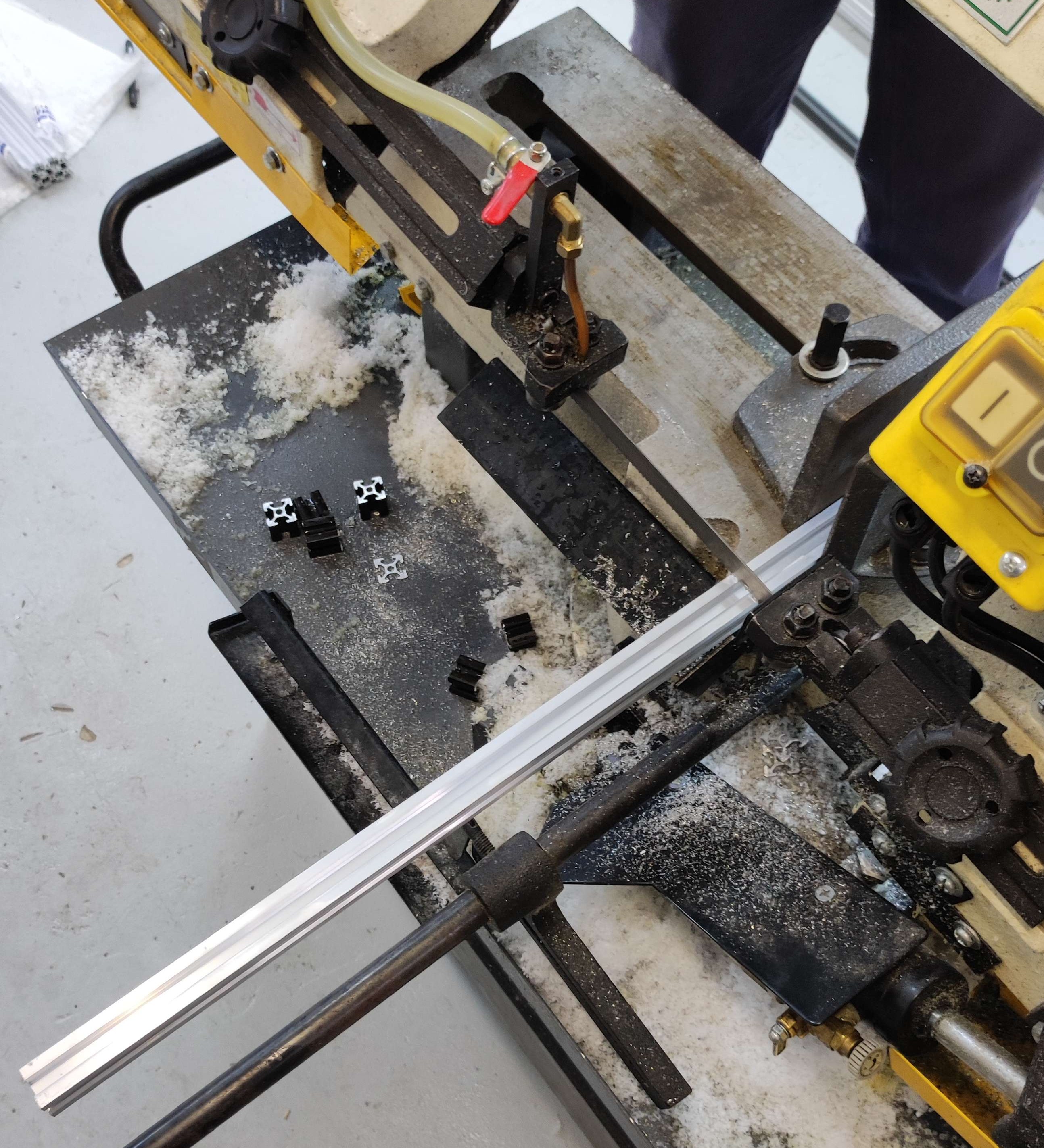
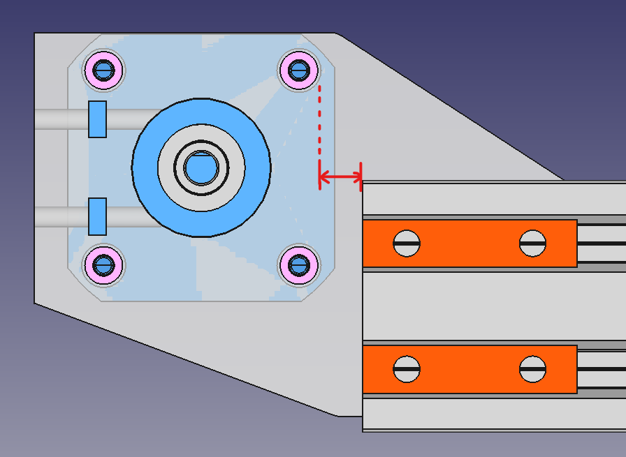
The 20x40V profile doesn't need to have an exact length (in red). It just needs to be long enough to avoid colliding with the pink SEP-5-20.V1 shown in the image, and there should be enough space to adjust the positions of the assemblies with respect to the profile. This adjust can be made through the adjustment of the orange 2020_DOUB_TWLO_M4 parts.
Step 3: Assemble the actuator
Assemble the X-carriage
Assembling the X-carriage takes a few steps:
-
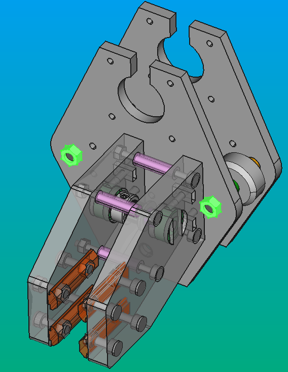
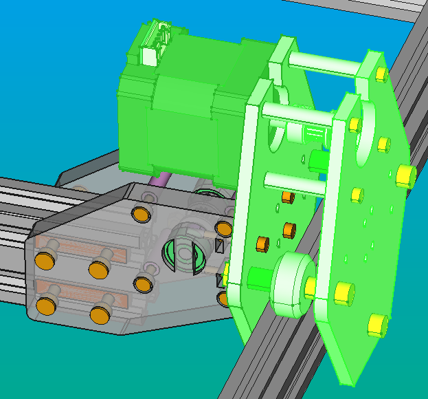
Before placing both X-axis plates (CARB-XZ-PL and CARB-XX-PL), you need to insert four M5 screws (2 x 45 mm and 2 x 35 mm) in the CARB-XZ-PL:
-
The longest ones goes into the holes where you will also place the eccentric nut.
- The shortest ones goes into the remaining two holes.
- Put the M5 eccentric nuts (Yellow) in the two lower holes of each plate. These should be pointing towards the direction of the other plate.
- Put two M5 x 40 mm screws in the same holes of the previous step and other two on the upper ones. These screws must be placed on the outside of the CARB-XX-PL (you will notice that the holes have a space for the heads of the screws).
- Put the two SEP-5-5.8 (light blue) on the upper screws, and then, put the V-Wheels (grey) on the four screw. After that, put the two SEP-5-10 (violet) on the upper screws and the two SEP-5-4 (violet) on the bottom ones.
-
Put the plates together, fitting the screws into the corresponding holes (fit the holes with the eccentric nuts, and the upper ones with the upper holes of the other plate.
-
Use the M5 nuts (YELLOW) on the outside of the CARB-XZ-PL plate and lock the screws. (orange)
- Finally you only need to put the M3 x 50 mm screws (yellow) on the holes at the sides of the plates and lock them with the M3 nuts (orange) on the behind part of the CARB-XZ-PL.
Assemble of the Y carriage
Note
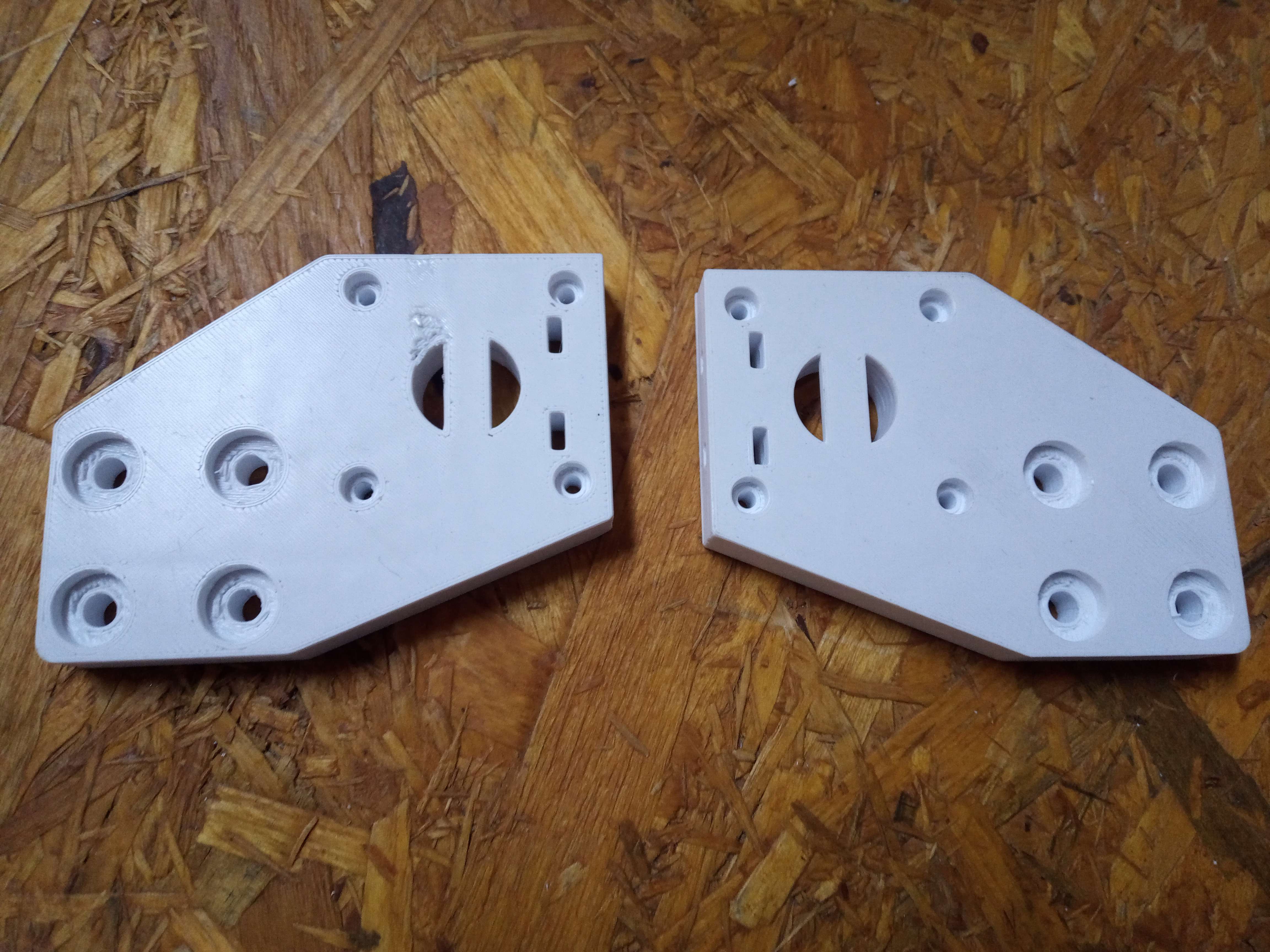
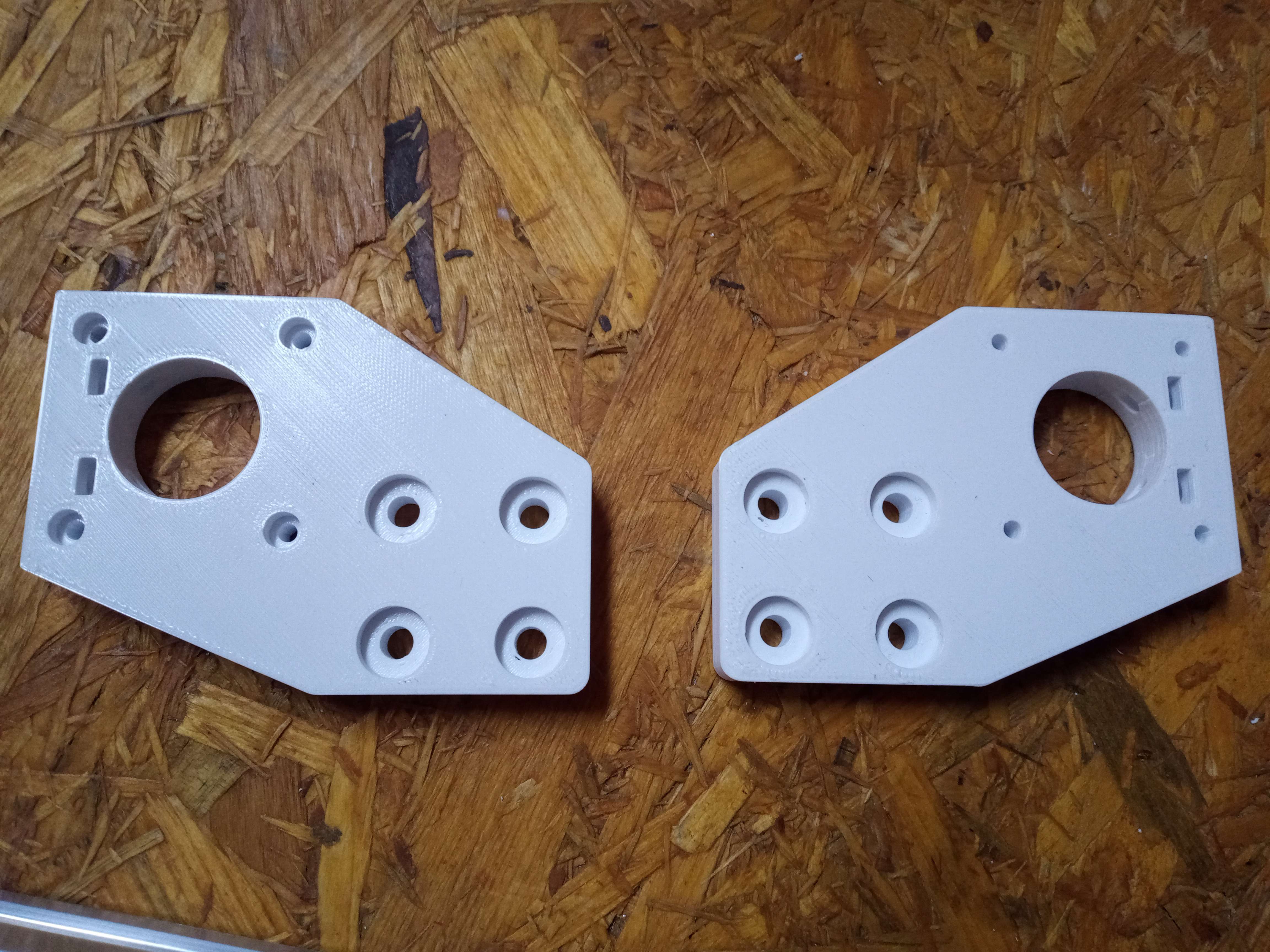
Before beginning the assembly of the Y axis carts, the structure frame must be assembled. You will need two CARB-XY-PL.V1 for each carriage.
- First, align the CARB-XY-PL.V1 with the M3 holes of the plates for each assembly (AS-XY-PU.V1 and AS-XY-ST.V1). Then, secure four M3 x 20 mm screws into them and fasten them with four M3 nuts placed inside the rectangular holes (purple) intersecting with the M3 holes on the plates.
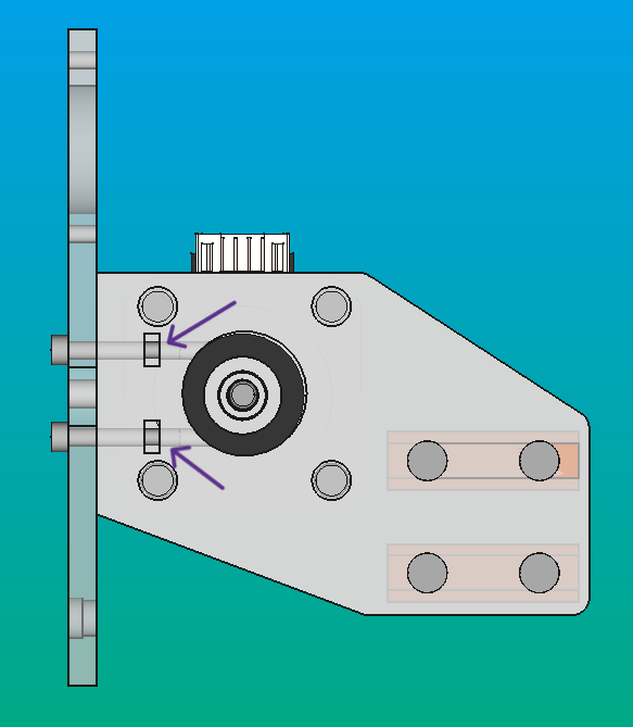
Tip
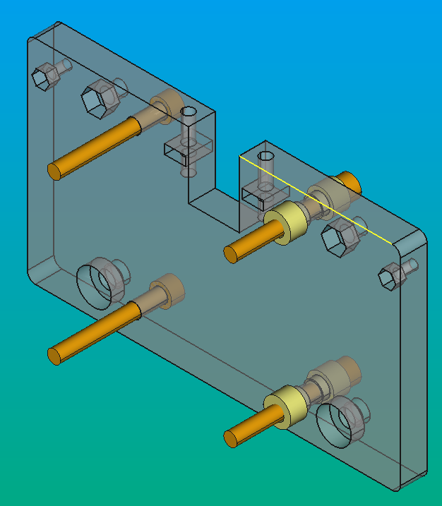
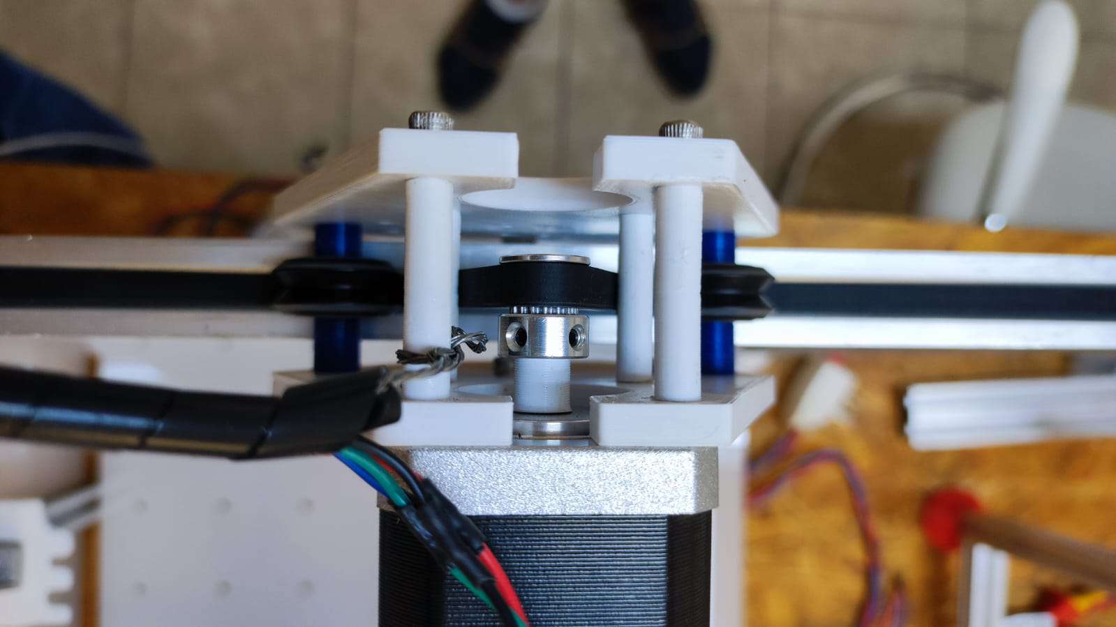
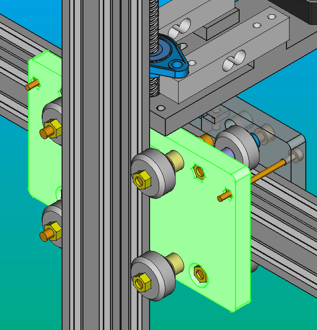
Make sure that the bottom hole is aligned as shown in the image below; both plates should have these holes in this way, with the part with the larger diameter on the inside of the carriage.
- Next, insert two M5 x 40 mm screws (light green) into the side holes of the other CARB-XY-PL.V1. Prioritize placing the SEP-5-6.2.V1 (orange), followed by the M5 V-wheels (grey), and then the SEP-5-10.2.V1 (green) on each screw. Pass an M5 x 40 mm screw through the holes until they protrude completely.
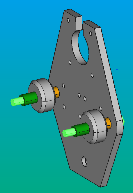
- Join the two CARB-XY-PL.V1 pieces using the M5 screws (light green), securing them with M5 nuts on each screw.
- Affix a stepper motor to the upper side of the CARB-XY-PL.V1 using four M3 x 40 mm screws (light green) and a SEP-4-27.4 (red) for each screw to ensure proper separation between each plate.
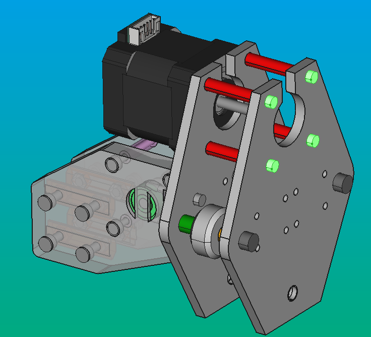
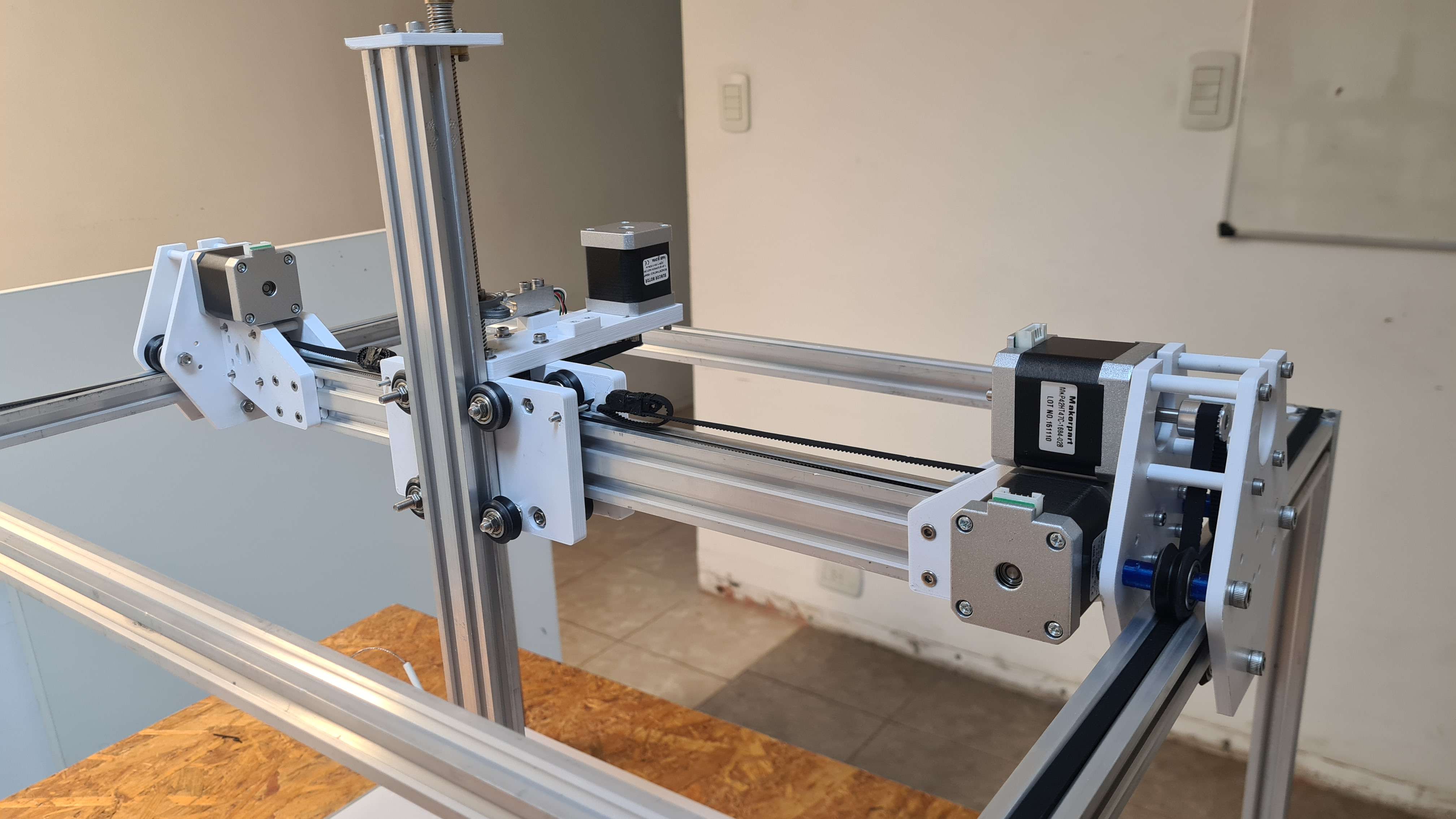
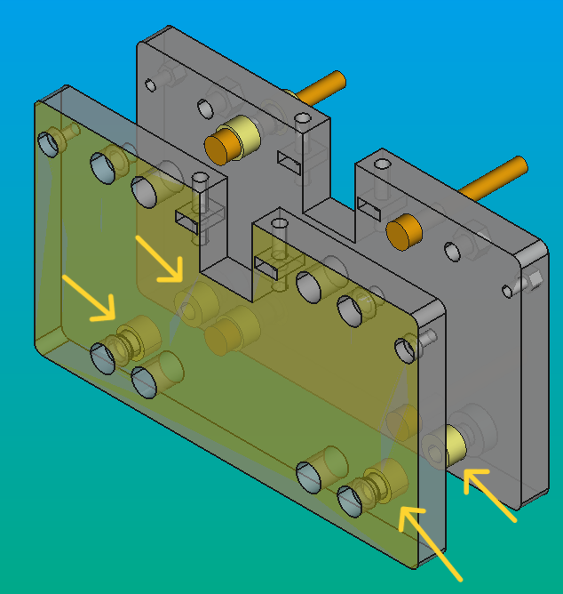
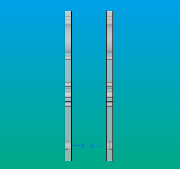
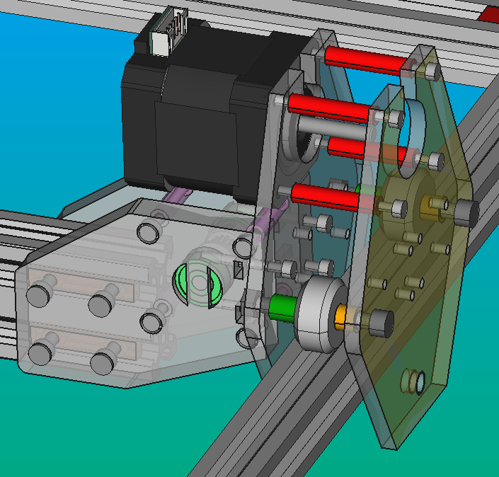
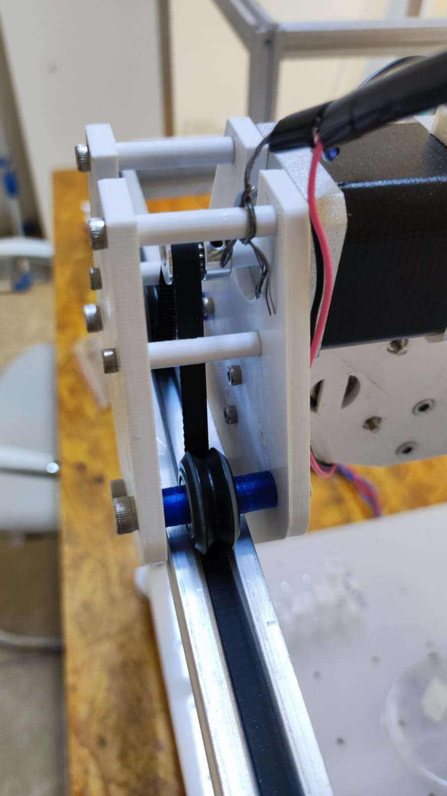
- Align the wheels of both carriages with the 20x20 V-profiles of the structural frame as shown in the image. If you don't align and support both carriages simultaneously on the 20x40 V-profiles, it may cause a rotation around the axis of the profile.
Note
The next step should be taken upon completing the assembly of the linear actuators for each axis. If not done in this way, it will complicate assembling the X-axis carriage onto the 20x40 V-profile.
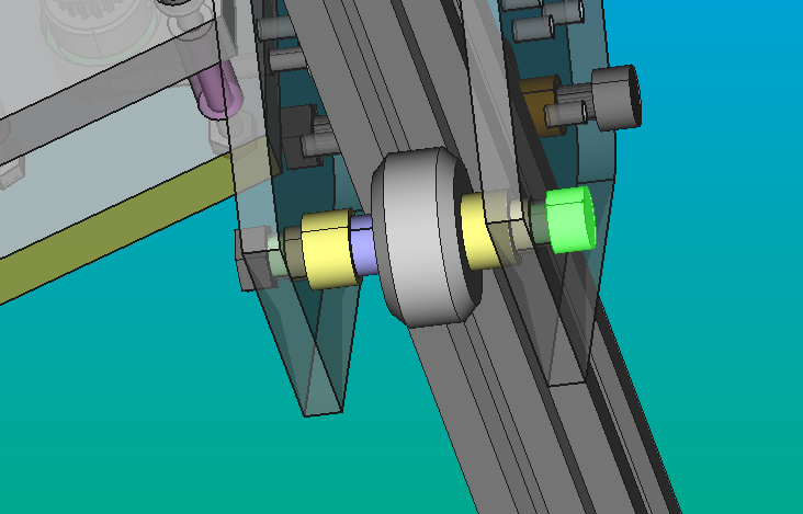
- Finally, install the wheel on the bottom side of the carriage. Begin by placing the M5-NUT-ECC.V1 (eccentric M5 nuts, yellow) on each plate. Subsequently, add the SEP-5-4 (violet) and align the M5 V-wheel with the profile. Once aligned, insert an M5 x 40 mm screw (light green) as done previously with the two above, and secure it with an M5 nut.
Info
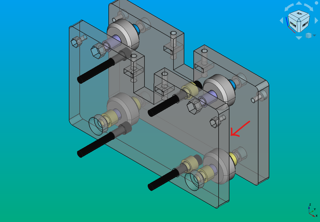
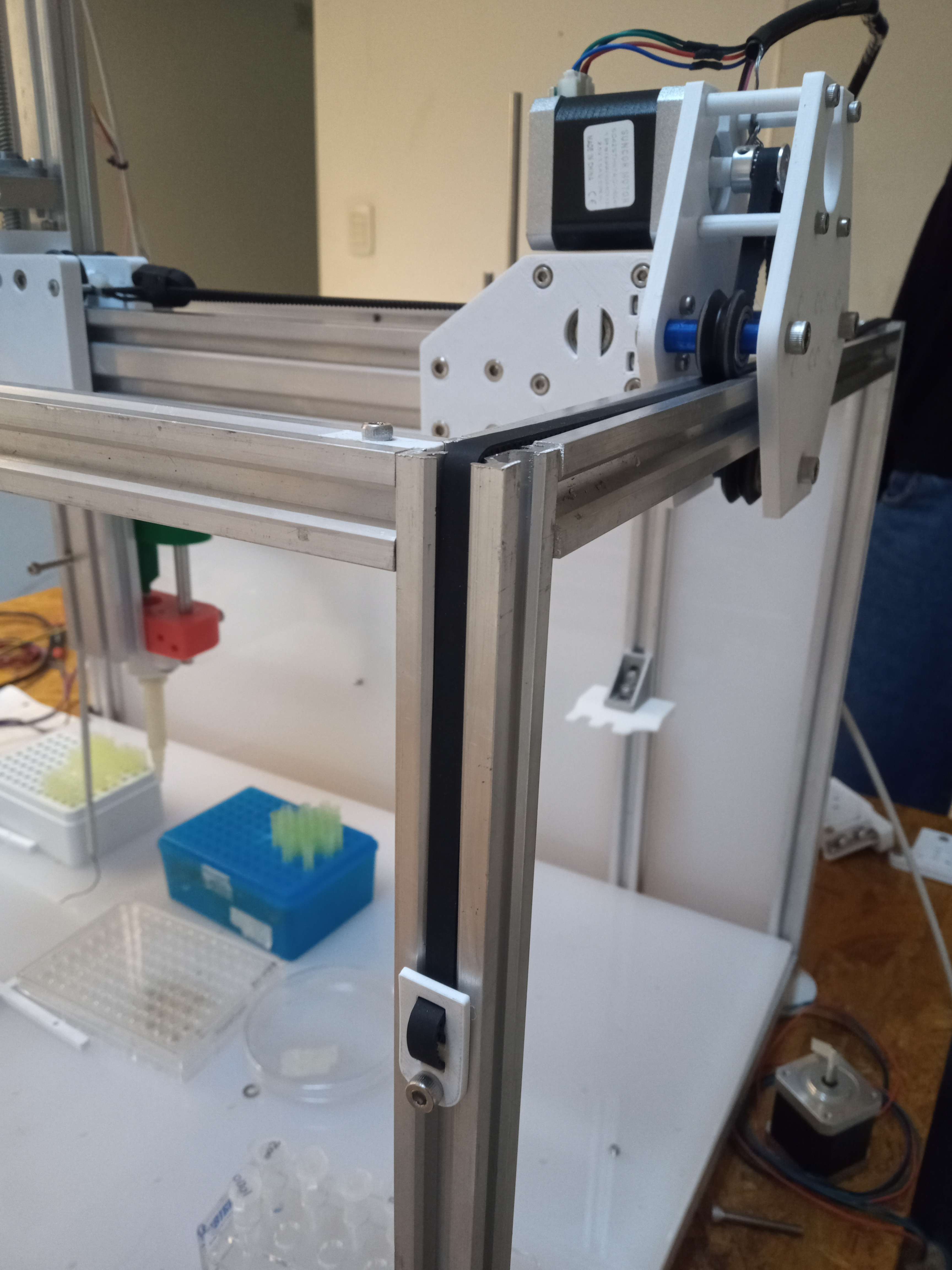
You can repeat this steps while assembling the Y carriage with the stepper motor. To do so, make sure to put it in a mirror position as shown below (red).
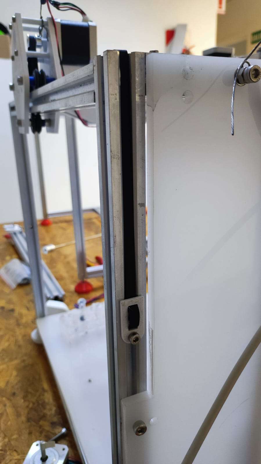
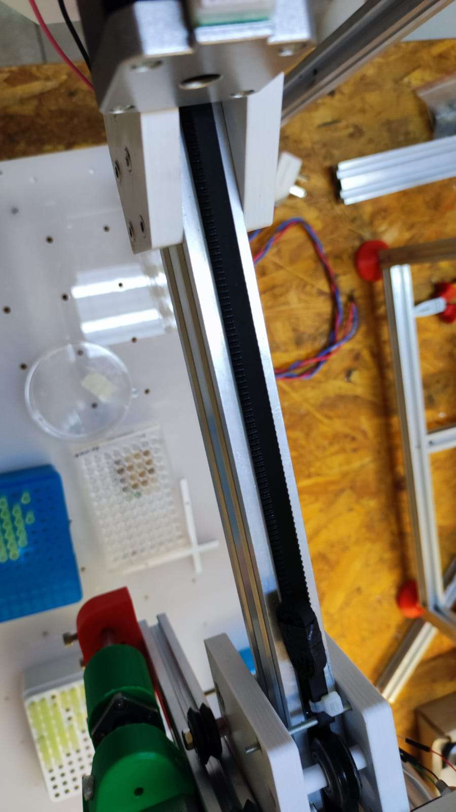
- The belt can be added once the assembly of the Y carriage is completed. It should be adjusted using a "belt end clamp", an M4 screw, and a nut from bellow. It is secured to one of the vertical 2020 profiles of the structural frame. One end of the belt can be adjusted, while the other end should pass under the upper wheel of the carriage on the same side. It then goes to the upper stepper and under the other upper wheel. By doing this, the end can be adjusted to the opposite 20x20V profile in the same way as the previous one.
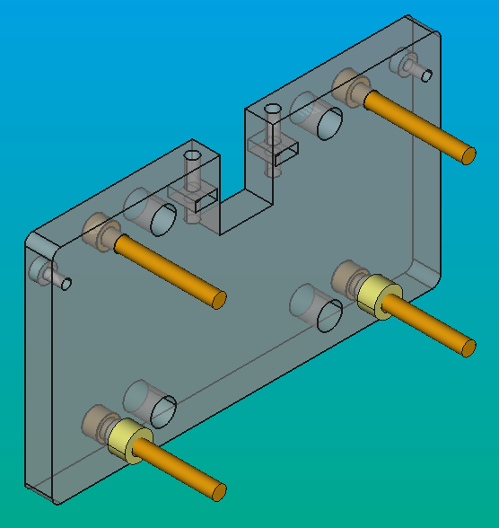
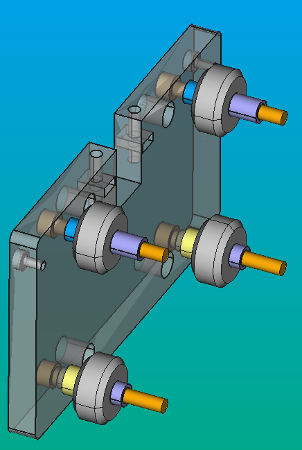
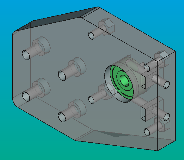
Assemble the actuator
- Put the rolling-element bearings (Green) into the holes of the CARB-XY-PU1.V2 and CARB-XY-PU2.V2 pieces.
-
Then insert in order:
-
SEP-5-3.1V1 (pink)
- one of the GT2 16T pulleys (grey)
- SEP-5-8.1V1 (purple)
on the 5 mm bar.
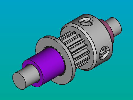
- Fit the step 2 pieces inside the hole of the Rolling-element bearing that is embedded to the CARB-XY-PU1.V2. You need to put the GT2 16T in the same orientation as the one on the motor stepper.
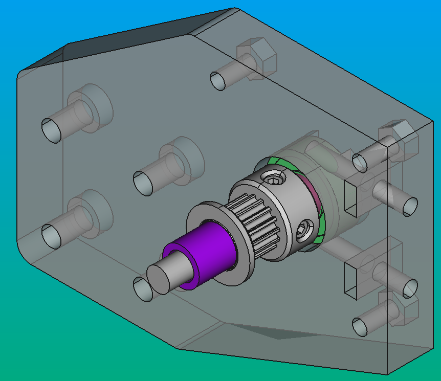
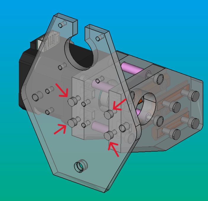
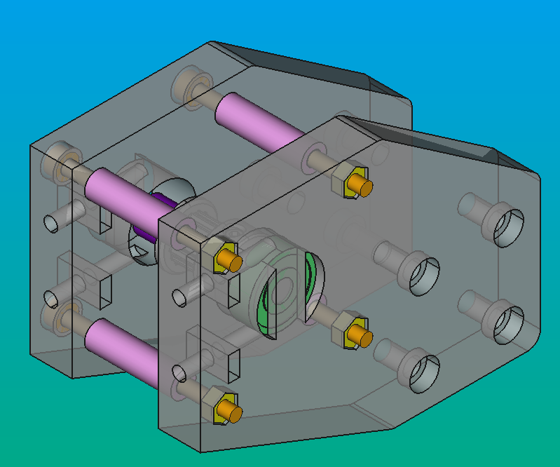
- Put the rear parts (CARB-XY-PU2.V2 and CARB-XY-ST.V3-MIRROR) and fit the M3 screws (orange) on the front print pieces (CARB-XY-PU1.V2 and CARB-XY-ST.V3) until the SEP-5-20V1 (pink) fit completely.
- On this part you must fit the four M3 nuts on the holes CARB-XY-PU2.V2 and the stepper motor behind the CARB-XY-ST.V3-MIRROR, and screw the screws to lock them (yellow).
Info
At this moment you must have the assemblies for the motor and the pulley. These assemblies will be named AS-XY-PU.V1 for the one with the pulley and AS-XY-ST.V1 for the one with the stepper motor.
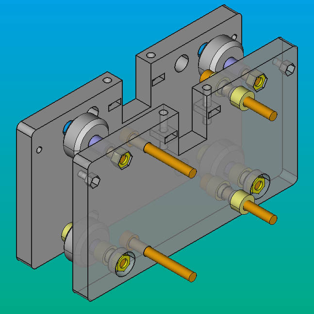
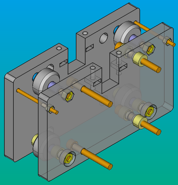
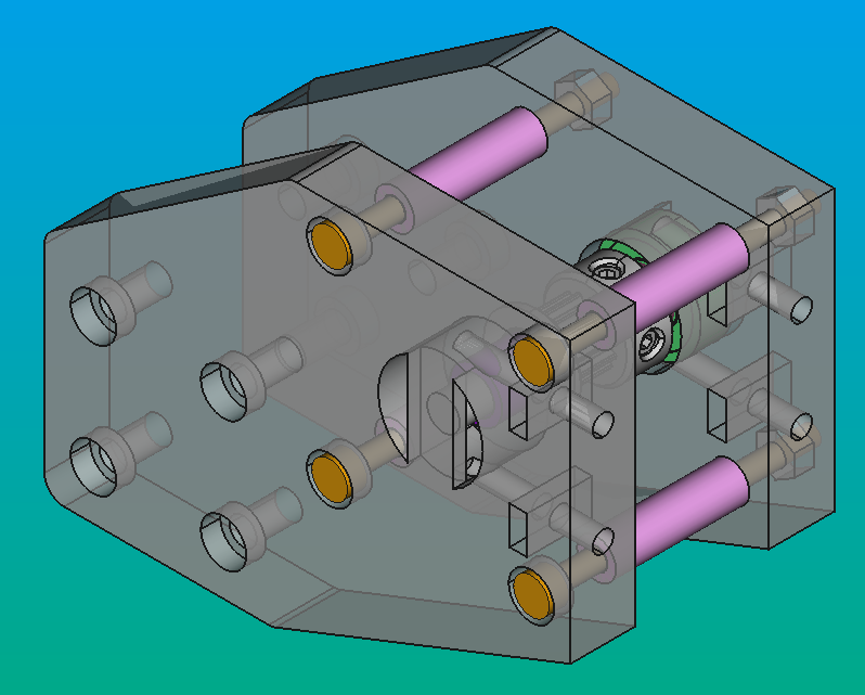
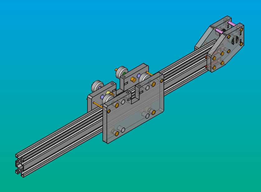
- Fit the M4 nuts on the 2020_DOUB_TWLO_M4.V1 and put them on the 20x40 V Profile.
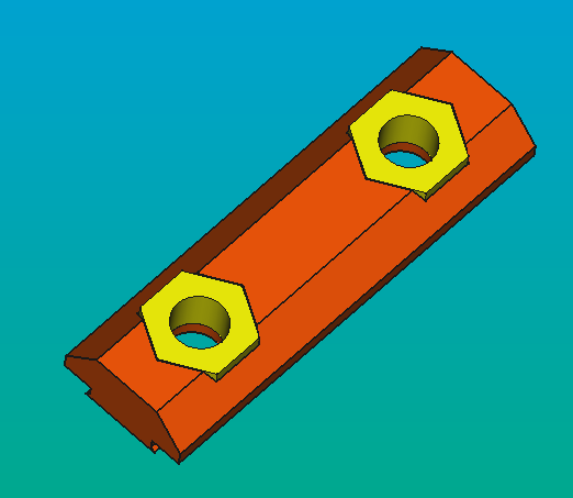
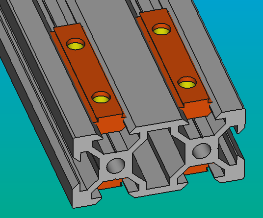
- Put the 20x40 V profile inside the two major pieces of the pulley´s assembly until the holes of the 2020_DOUB_TWLO_M4.V1 and the pieces match, then screw the M4 screws until the pieces can't move (yellow).
Info
With this part you can change the distance between the motor's and pulley's assemblies (AS-XY-ST.V1 and AS-XY-PU.V1 respectively) to the 20x40 V profile. You just need to unscrew the M4 screws until you can move the pieces through the profile.
- Before doing the same with the stepper pieces, you must fit the X-carriage to the profile. You will need to make some pressure, but not too much. If the carriage does not fit, you can adjust the eccentrical nuts to change the position of the V-wheels and make it fit. After that, you can fit the stepper motor assembly
Info
You can fit the Y carriages to the assemblies after or before the 7 step, it depends on how it's made more comfortable for you.
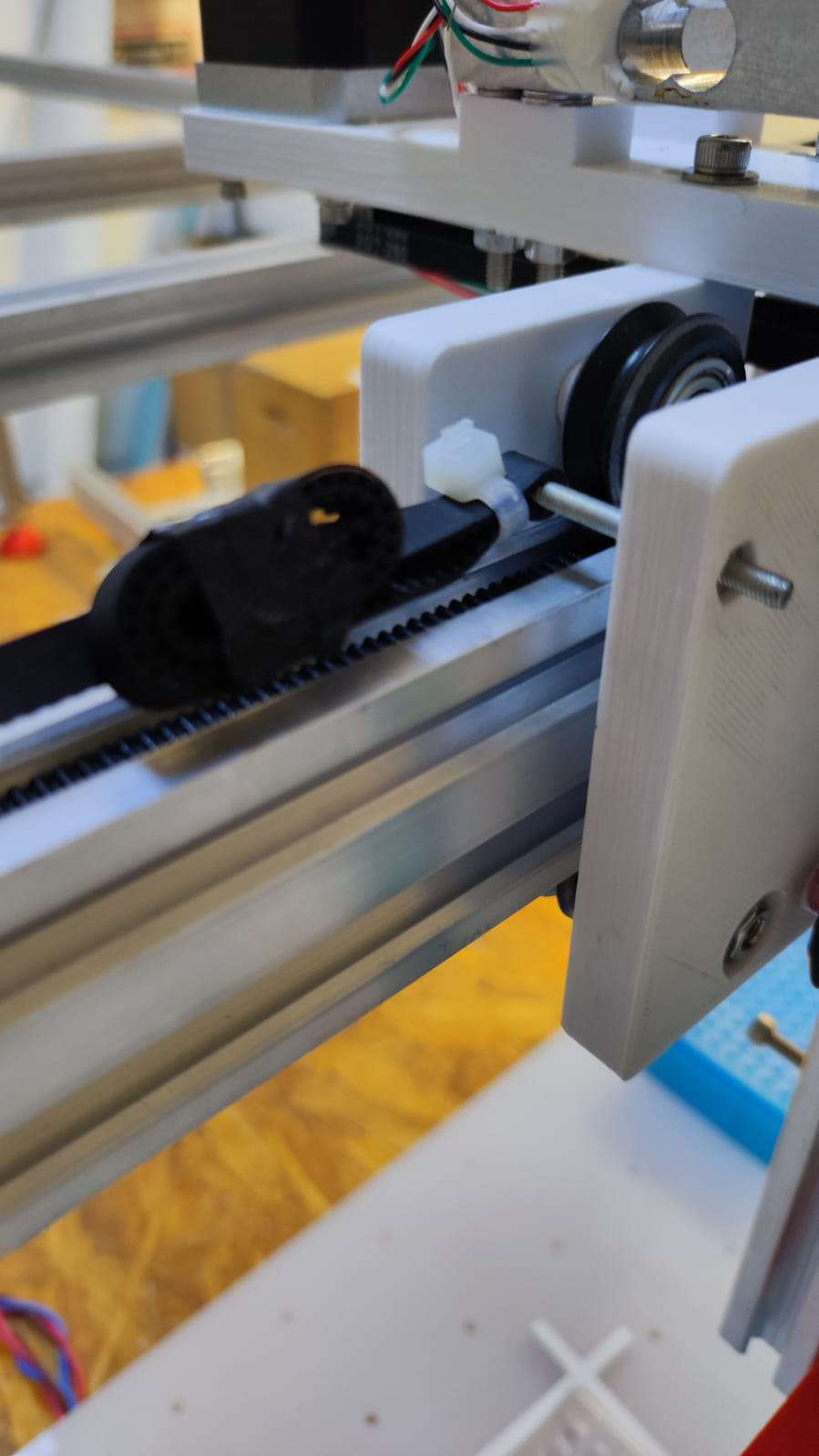
- When you finished assembling, you can put the GT2 belt. It must join the pulleys on each side and the M3 screws that are in the X-carriage. You must adjust the belt and use some seals to lock it.
Mount the actuator to the structure
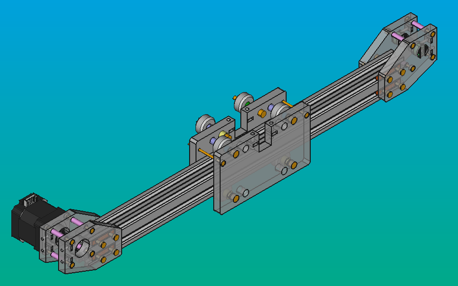
Once the entire motion system is finished, you can attach it to the structural frame following the 6th step of the assembly guide of the Y-carriages.
Remember that both carriages must be installed at the same time to avoid any rotation on the axes of the 20x20 V-profiles of the structure.
Finally you can put the GT2 Timing Belt on the X and Y axes.
Interactions
The XY-axes linear actuator works as a movement system and a platform for the Z-axis Linear Actuator.
It interacts with the Z-axis through the plate "CARB-XZ-PL" mounted on the X-carriage.
It also interacts with the structural frame through the Y-carriages. These are joined through the stepper and pulleys pieces. These pieces are:
- CARB-XY-PU1.V2
- CARB-XY-PU2.V2
- CARB-XY-ST1.V3
- CARB-XY-ST2.V3
Design
The design of this part was thought with the idea of having a single stepper motor and a pulley on the X-axis linear actuator. The stepper motor and the pulley would be in a perpendicular direction to the profile. The brackets were designed taking into account the measurements of the GT2 16T pulley.
In a first attempt, we tried to make the model with one bracket for the motor and one for the pulley. These had a width of 10 mm for the pulley and the motor, and 3 mm for the 20x40V profile, but after printing them, we noticed that these models were not strong enough nor did they offer the necessary rigidity to support the structure.
In order to give the brackets rigidity and greater resistance, we decided to give them a width of 10 mm in their entirety. Furthermore, we added an equal piece to each grip so that they can support the 20x40V profile from both sides.
The following factors were taken into consideration for the design of the X-carriage:
- The dimensions of the 20x40V profile.
- The height of the GT2 16T pulleys.
- The distance between the holes needed to fit the Z-linear actuator.
- The possibility to change the adjustment of the V-Wheels.
Also it was necessary to have in mind the space that the X-carriage had to move along the 20x40V profile. Moreover, it was also necessary to consider the length of the X-carriage and the measurements of the brackets that join the stepper and the pulleys.
The pieces were generated using FreeCAD. We made 3D-printed parts since it's cheap and easy to edit depending on the needs of the user.
Models
The latest versions of all files will be available at this link
-
Profiles: custom part
- Material: Aluminum 20x40 V-Slot
- CAD: 2040V-490.V1.FCStd
- Drawings: [2040V-490.V1.FCStd]
- Part number: 2040V-490
-
CARB-XX-ST: custom part
- Material: PLA
- CAD: CARB-XX-PL.V1.FCStd
- Drawings: [CARB-XX-PL.V1_DRAWING.pdf]
- Part number: CARB-XX-PL
-
CARB-XY-PU1 and CARB-XY-PU2: custom part
- Material: PLA
- CAD: CARB-XY-PU.V2.FCStd
- Drawings: [CARB-XX-PU1.V2_DRAWING.pdf]
- Part number: CARB-XY-PU
-
CARB-XY-ST1 and CARB-XY-ST2: custom part
- Material: PLA
- CAD: CARB-XY-ST.V3.FCStd
- Drawings: [CARB-XY-ST.V3_DRAWING.pdf]
- Part number: CARB-XX-PL
-
CARB-XZ-PL.V4: custom part
- Material: PLA
- CAD: CARB-XZ-PL.V4.FCStd
- Drawings: [CARB-XZ-PL.V4_DRAWING.PDF]
- Part number: CARB-XZ-PL
-
2020_DOUB_TWLO_M5.V1: custom part
- Material: PLA
- CAD: 2020_DOUB_TWLO_M5.V1.FCStd
- Drawings: 2020_DOUB_TWLOCK_M5.V1_DRAWING.PDF
- Part number: CARB-XZ-PL
Development
These 3D-printed parts were designed in FreeCAD 2.1 and 2.0, then exported in the FCStd format for slicing. They were printed on an Original Prusa i3 MK3 using STL files. Most pieces were inspired by Jubilee's designs for compatibility between these CNC machines tools.
To learn more about these file formats visit here.