Baseplate
Baseplate and Platform Curbs
Info
Discord forum thread License: CERN-OHL-S-2.0
Overview
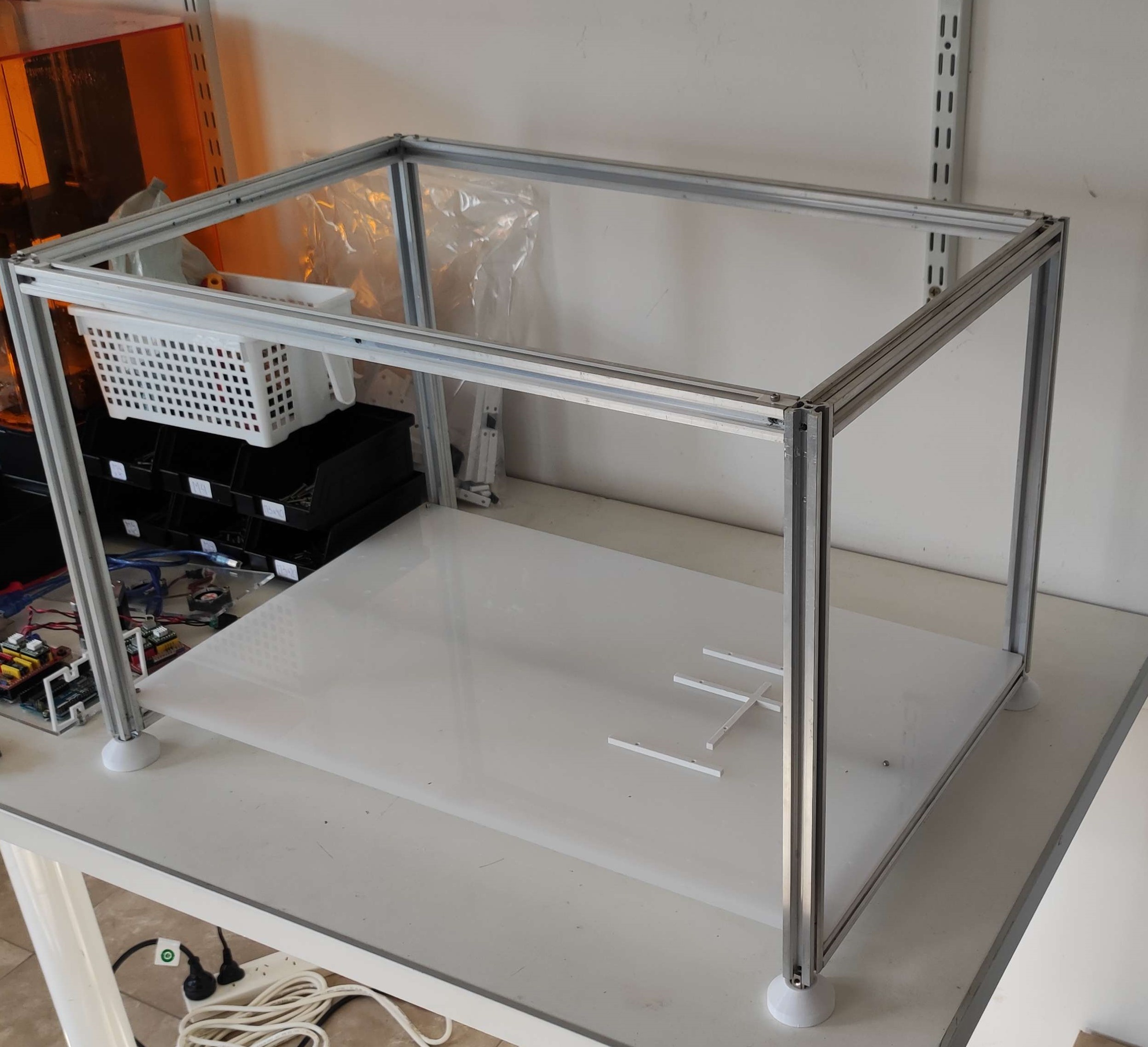
The baseplate is supported by the machine's structural frame, and it in turn supports various "platforms", such as tube and tip racks. It's nothing more than a "table" with regular holes on which "curbs" are attached, allowing you to align objects on its surface.
Other automation projects call this part a "deck" (e.g. PLR, Duckbot, etc.).
Throughout this section you will find general guidelines for building Pipettin bot's baseplate, technical drawings, manufacturing instructions and other options you could consider for your Pipettin bot.

Usage
Before you start using the Pipettin bot, you need to mount the baseplate on the structure. You need to make sure that the baseplate is stable and its alignment with the structure is accurate and repeatable.
Warning
Don’t move the baseplate while the robot is working. If you do so, you will lose the calibration.
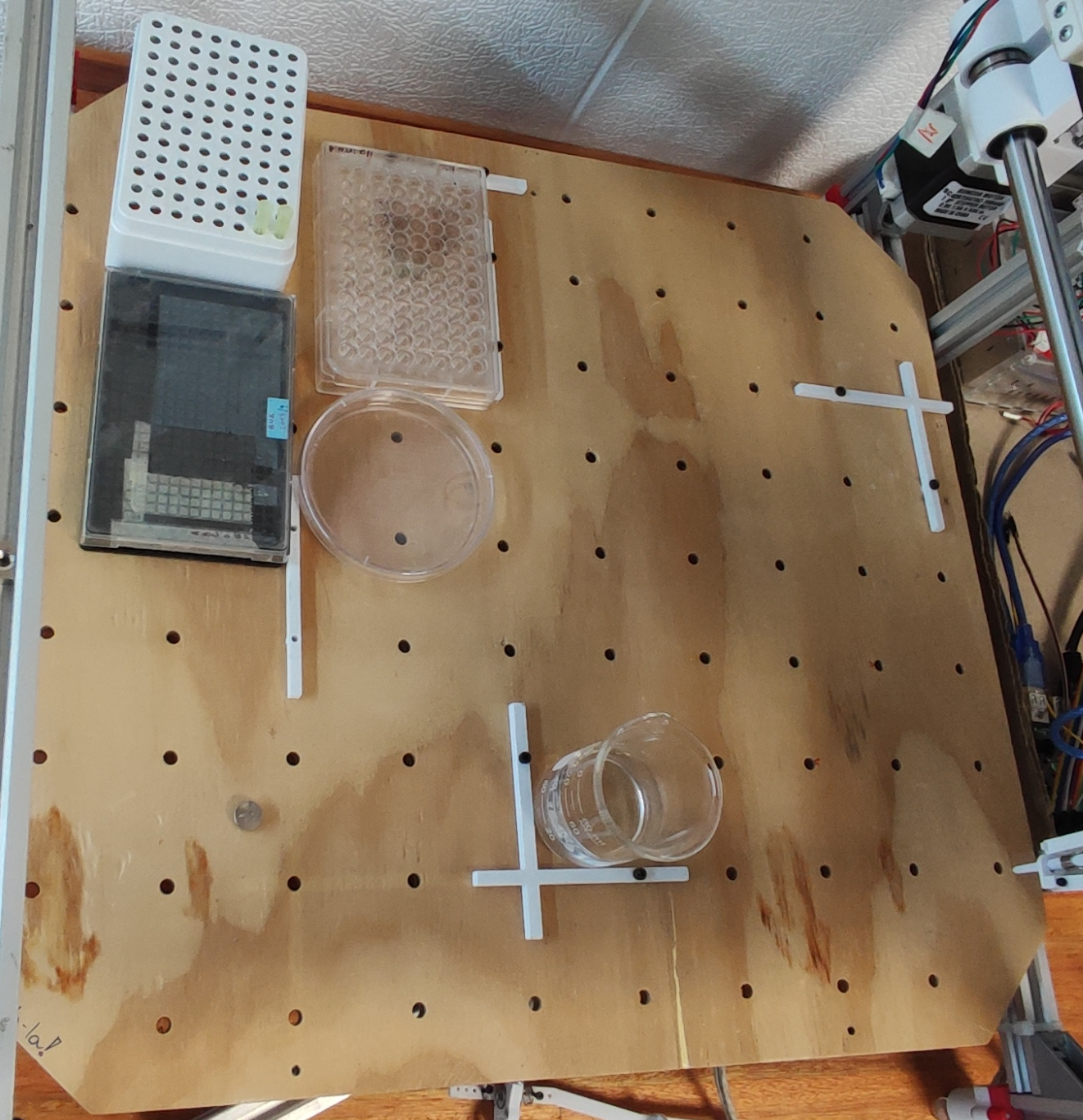
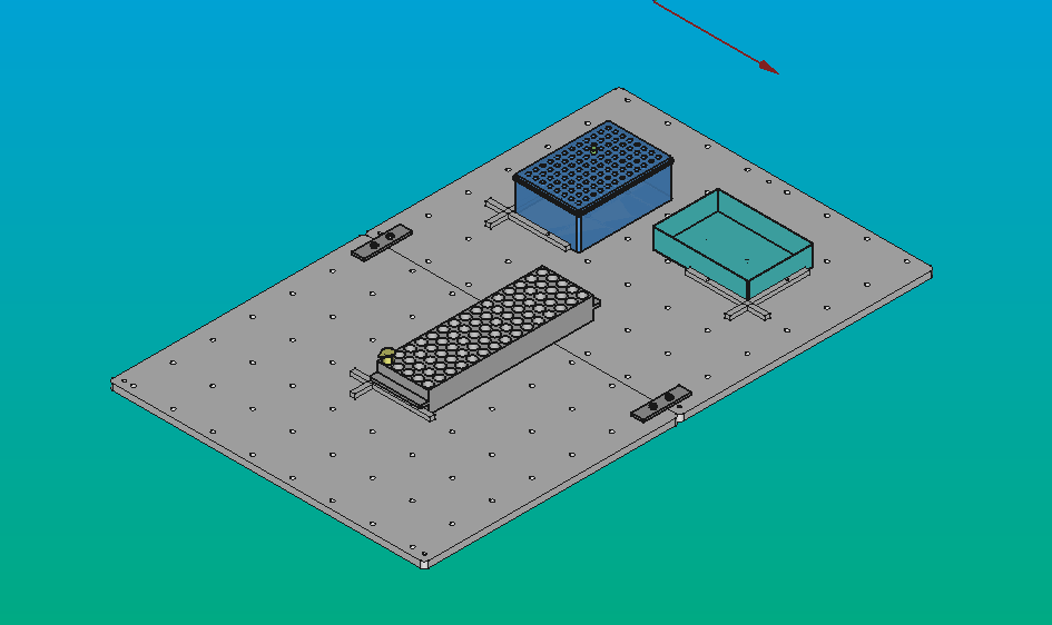
To mount the different types of platforms (discard box, standard well plates, tube racks, etc), the baseplate can be fitted with "curbs". These are small 3D-printed parts that can be inserted and fixed to the baseplate, which allows platforms to be placed and removed, both effortlessly and accurately.
Curbs are placed as a physical guide to the platforms on your workspace as shown below. Those guides are used to align objects relative to the machine's coordinates, both easily and consistently.
Info
Calibrations can be done without curbs. However, it might be difficult and it can result in location errors during the process.

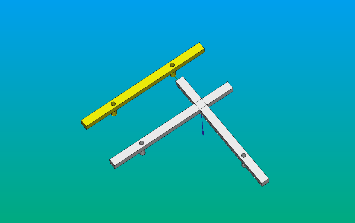
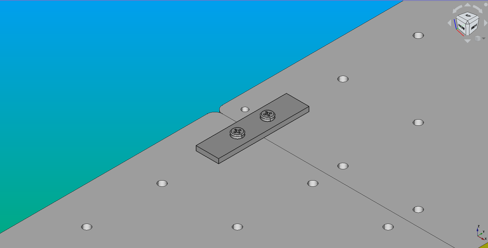
When using the aluminium baseplates as uncoupled halfs, you must make sure that tip racks and heavy objects are placed within the triangle of the kinmatic coupling underneath. Otherwise, the force can tilt the baseplate. To solve this problem, the two halfs can be attached to each other with a 'coupling' (two small plates secured with screws).
Info
Our aluminium baseplate consists of two halfs. This is beacause the full-size baseplate did not fit inside the workspace of our CNC router. If your router is large enough, consider milling it in one piece.
Assembly
Stepwise guide
A nice and updated step-by-step guide for the assembly is available:
Instructions below can be considered development notes.
Video
Watch a short video about the baseplate assembly process.
Manufacturing
Safety and Warnings
Take this into account before using heavy tools and CNC machines.
- Personal safety: wear protective glasses, closed-toed shoes and ear protection. Do not wear jewelry and tie your hair.
- Safe operation: before starting the machine, make sure materials are centered on the baseplate, secure the protective screen, and turn on and activate the exhaust system or dust fan. Do not interfere with the machine until the process is finished.
- Fail-safe devices: Familiarize yourself with fail-safe devices.
- Cooling and cleaning: When finishing the piece, let it cool before removing it, and clean the remains
- Safety equipment: Do not remove any safety equipment while following the procedure above.
Required skills and resources
As stated in the main assembly guide, you'll benefit from access to a CNC router. There are rather common, but you can manage without one.
The main objective here is to drill on the baseplate: - A regular grid of holes, for the curbs. - Three holes for the kinematic coupling to the rest of the machine.
Your options:
-
Hire a CNC machining service is to drill the regular grid of holes on the baseplate, and the kinematic coupling holes.
- The baseplate should be easy to machine in a cheap laminated wood or anything fancier.
-
Drill your own holes.
- The precision requirements for the baseplate are not too high. Keeping stuff square is the only requirement.
- Good use of a ruler, carpenter's square, and hand-held drill should suffice.
-
If you are willing to permanently attach stuff to the baseplate and the machine, you only need a plank of appropriate size and some screws. Skip the rest. Check out the other versions of the baseplate here.
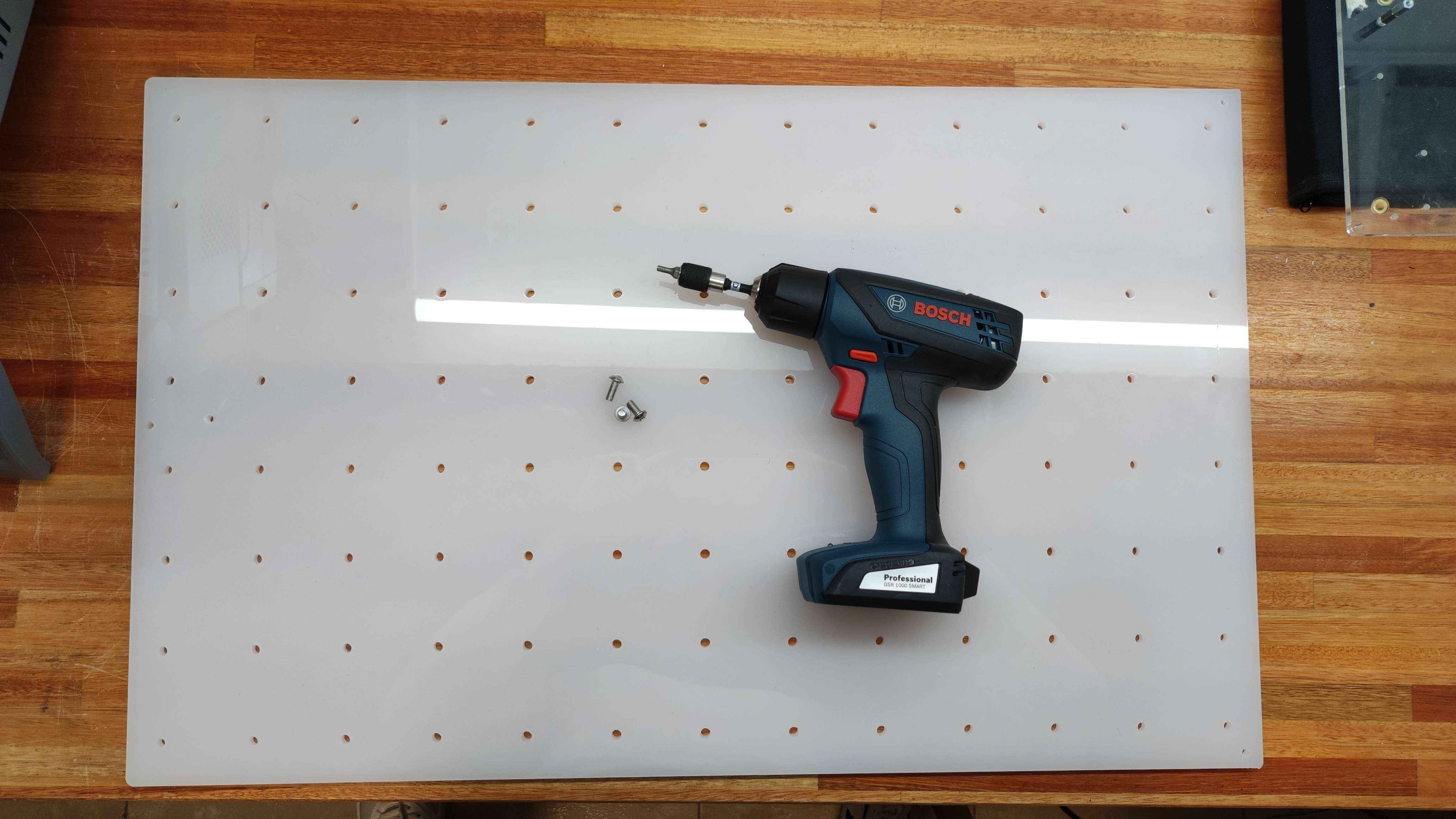
Step 1: Gather the parts
Parts and materials:
- Acrylic, hard wood, or 2x aluminum stock material for cutting.
- Structural frame, step 1 of the assembly guide.
- 3x M5 screws, round head (or 6x M5 screws in case you are using two aluminum baseplates).
- Curbs.
- Flat metal coupling (in case you are using two aluminum baseplates).
Tools for assembly:
- Screwdrivers.
- Bubble level.
Step 2: CNC the baseplate
Links to CAD files listed in the sources page.
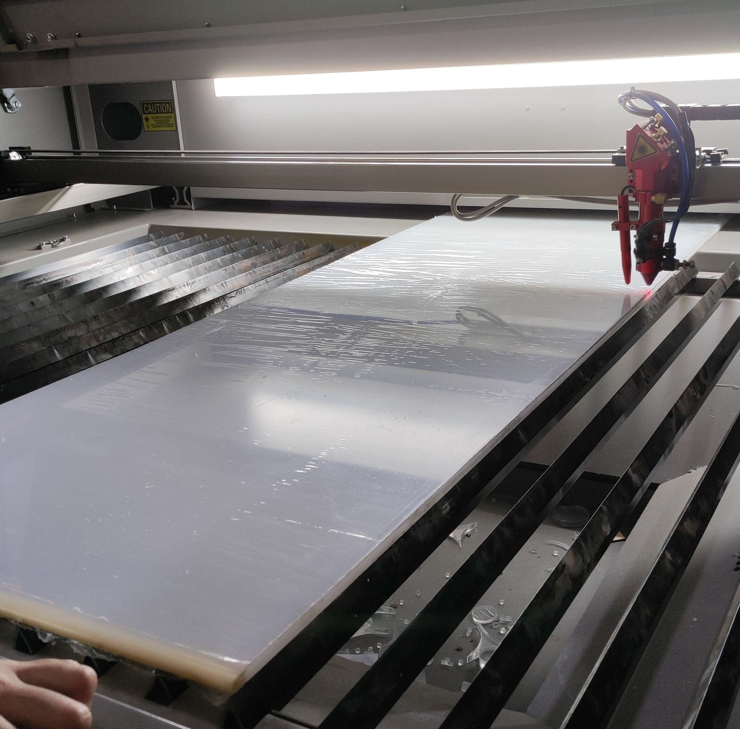
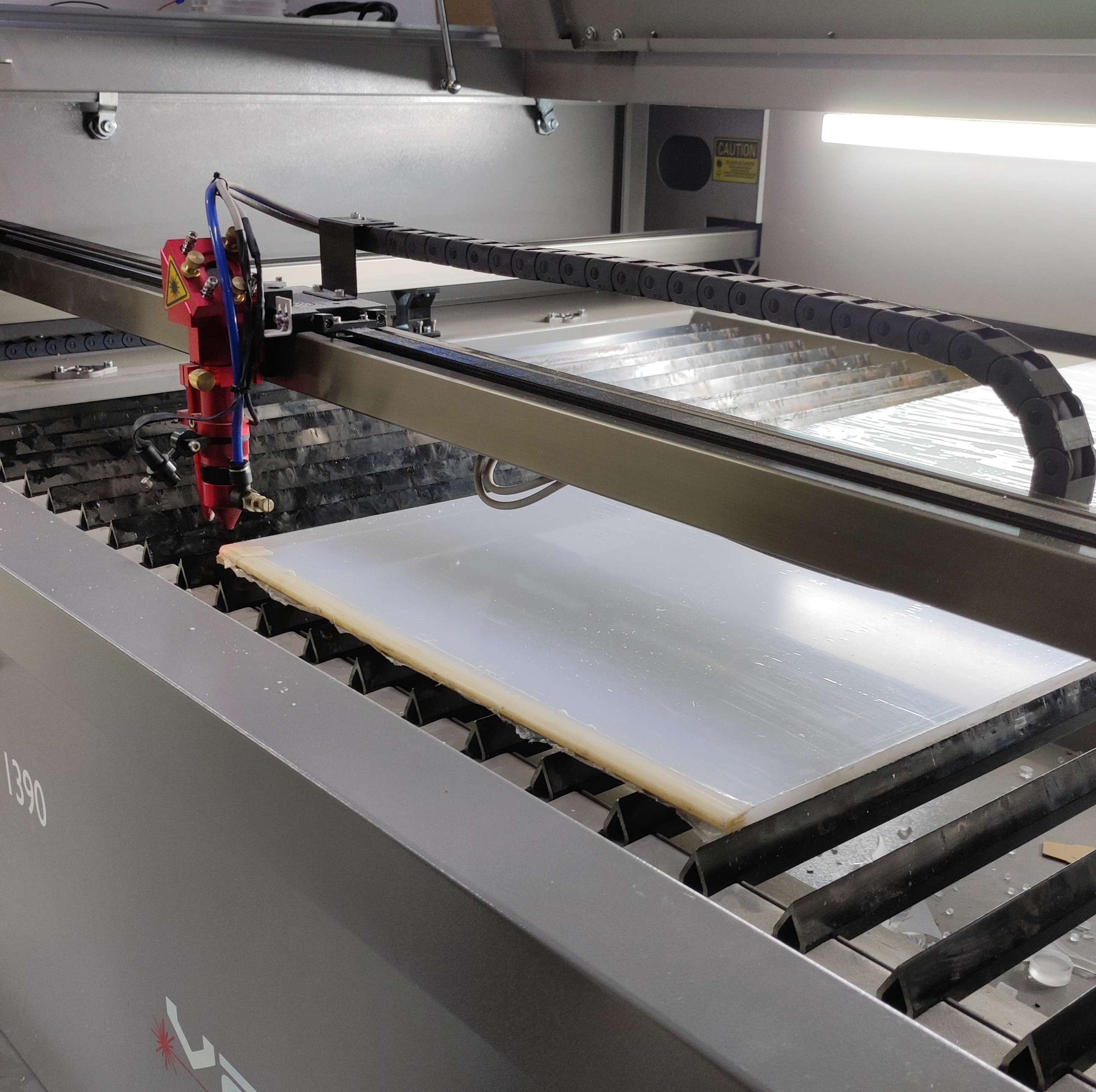
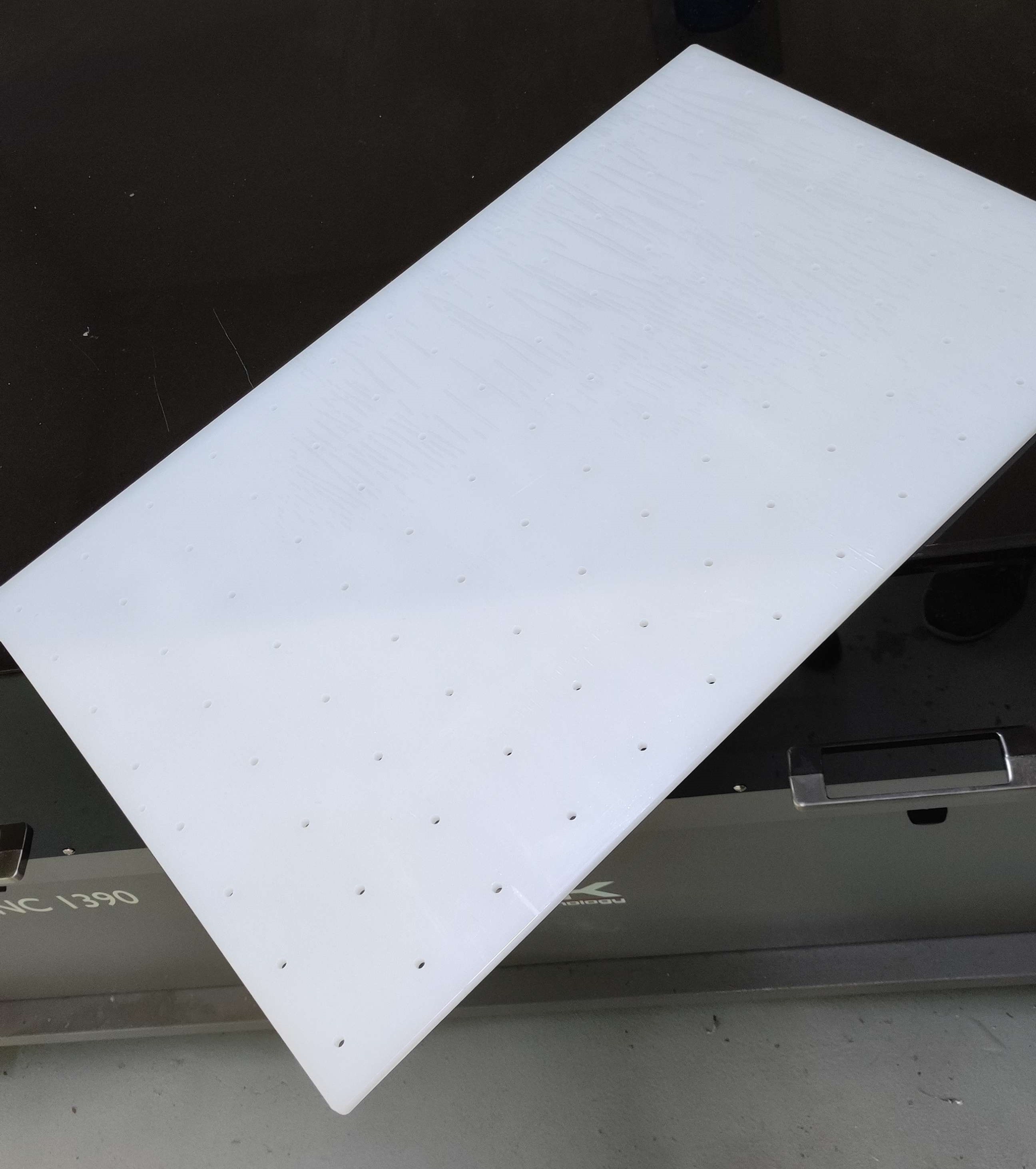
Acrylic baseplate
Materials
- Acrylic 1220 x 2440 x 10 mm
- Laser cutting machine: Laser CNC 1390 (Laser Machining Time: 00:13:46 approx.)
- Electric hand drill.
- M5 thread tap.
Procedure
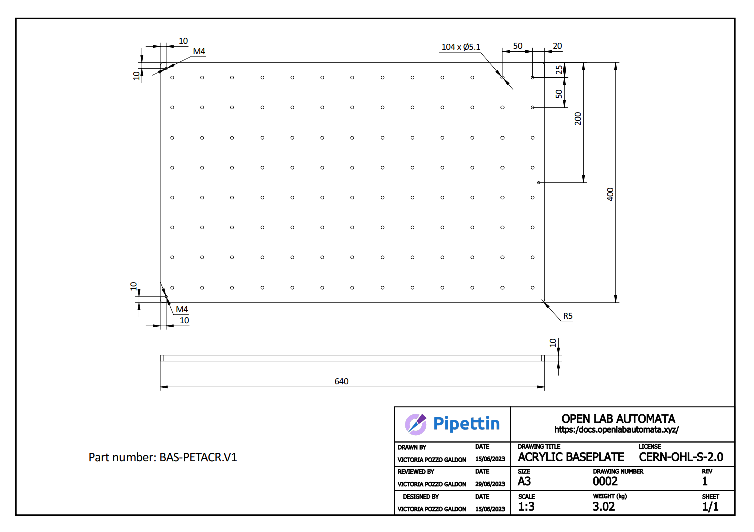
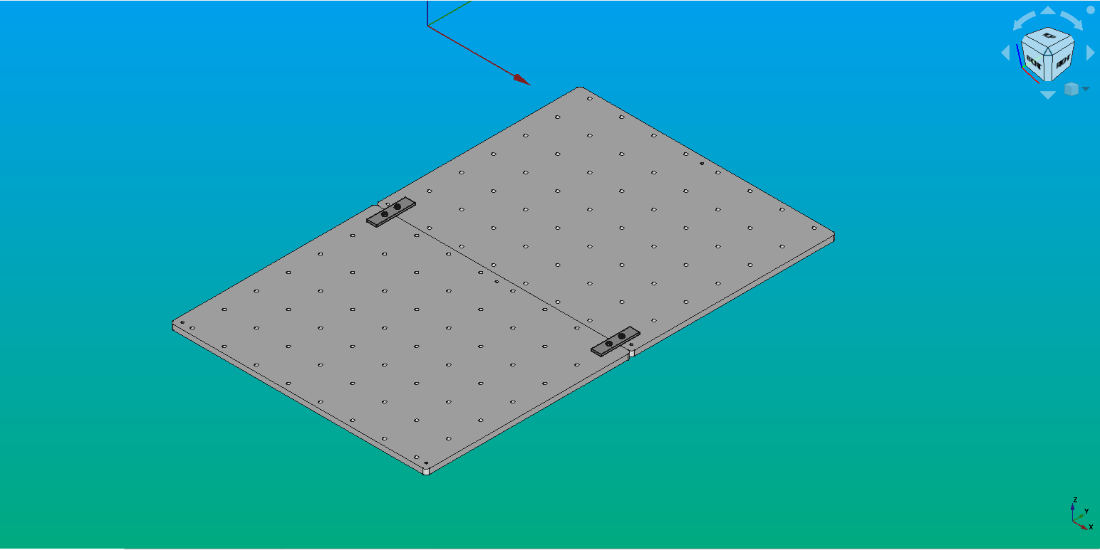
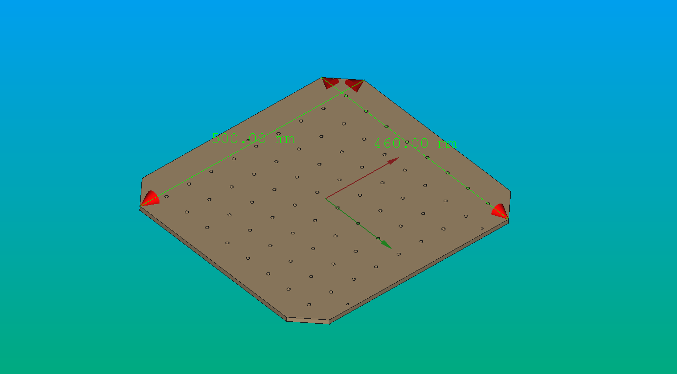
Adaptation of the Design: Before proceeding, review the measurements of your structure and adjust the dimensions of the Deck Baseplate accordingly. The drawing below is for a reasonable baseplate, compatible with the dimensions of the aluminium frame:
-
Preparation of the Design File: Make sure you have the drawing of the part in .DXF format. You can obtain it using the Part Workbench in FreeCAD by making a section of the baseplate model. Then, add this section to a TechDraw page, and export it as .SVG or .DXF, depending on the compatibility with the software you are using (in our case, LightBurn accepts both file formats, RDWorks accepts DXF).
-
Laser CNC Setup: Load the design file into the Laser CNC software (in our case, LightBurn Beta 0.8.07).
-
Place the acrylic material on the laser bed.
- Laser Configuration: Adjust the laser settings according to the following parameters:
- Focus: Set the distance between the laser head and the material. Some laser machines has an automatic approach system, and others require a manual adjust.
- Origin: Define the reference point of the piece. Consider the origin you determined in the program.
- Frame: Verify if the piece is within the cutting area of the material.
- Cutting speed: in our case, 5.0 mm/s.
- Cutting priority: you can set priorities to cut first some parts. We set as a priority the holes, to cut it first and then the border.
- Laser frequency.
- Laser power: in our case, 100%.
- Once the configurations are done, press the "Start" button to initiate the laser cutting process.
Aluminum baseplate
Materials
- Milling Machine (CNC).
- Plate of Aluminum 6061-T6. Dimensions: 410 x 330 x 10 mm
- End Mills (preferably hard metal).
Procedure
- First, securely fasten the plate to the CNC base. The optimal way to do it is by holding it using a vacuum table. If your CNC doesn't have one, use clamps, vises, clamping bolts, or other quick clamping systems to secure the part on the CNC work table. Then, once the holes are made, you can use those instead to hold down the piece.
- For the grid, drill through holes of Ø5.1 mm diameter, spaced 50 mm apart, and chamfer the edges.
- Then drill M5 threads for the three points of the kinematic coupling. These holes are for three screws, part of the kinematic system, used to restrict degrees of freedom of the baseplate.
- First drill an Ø4.3 mm hole through all.
- Mechanize the holes with an M5 screw tap.
- Face milling up to 9 mm thickness.
- Turn over the base and start face milling up to 8 mm thickness.
- Cut the plate to 400x320 mm rounding the edges and chamfering the borders.
- Finally, we anodize the plate.
Learning resources:
- CNC Vacuum Tables: http://www.cnccookbook.com.s3-website-us-east-1.amazonaws.com/CCCNCVacuumTable.html
- CNC Milling Process: https://get-it-made.co.uk/resources/cnc-milling-process-guide
- CNC Face Milling Tutorial: https://www.youtube.com/watch?v=jSrDB67yFoI
Info
In our case, we use two half-baseplates because the larger one did not fit on our CNC router. If you do so, be careful while putting heavy racks on top of the the two plate's junction, as it could tilt the baseplate. We solved it adding a 'coupling': it consists in two small plates secured with screws, as shown below.
Wood baseplate
Warning
This design is not up to date, but still relevant.
Ask your local wood-specialized CNC service to:
- Drill the grid: 6 mm diameter holes, 5 [cm] away from each other in both directions (center-to-center distance).
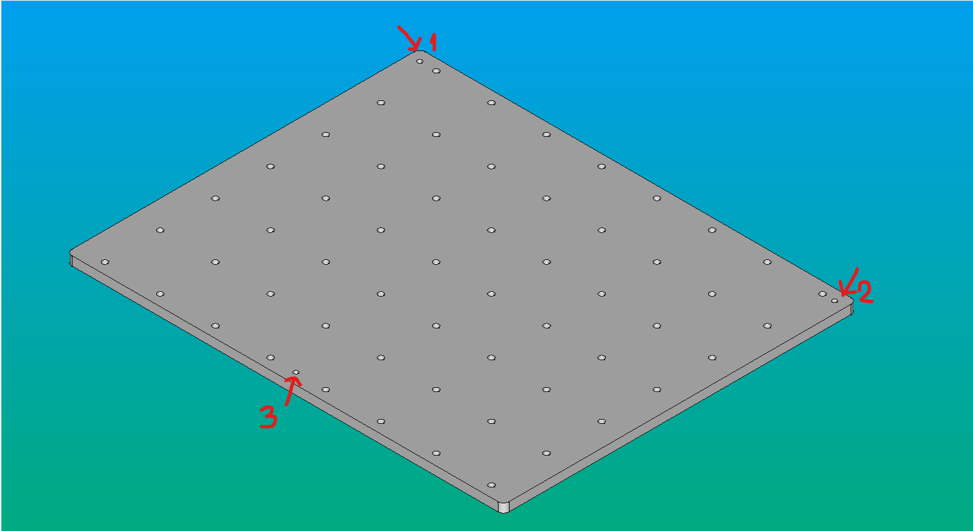
- Drill holes 1 and 2 on the same edge, 10 mm from the edge; they must align with the v-slot on the lateral profile (left image).
- Drill the hole 3 on the opposite edge, 30 mm from the edge; it must align with the v-slot on the crossing profile (right image).
- The precision of this step is critical to the general alignment of objects; the directions of the grid must be parallel to the CNC's XY axis.
The only concerns should be that the wood is relatively stiff or thick, and that it is flat enough.
Slight barnishing can help avoid warping, and cleaning when something is spilled on its surface. Other more resistant coatings can be applied, as long as they do not obstruct the grid or affect the kinematic coupling in any way.
Example:
Step 3: Coupling screws
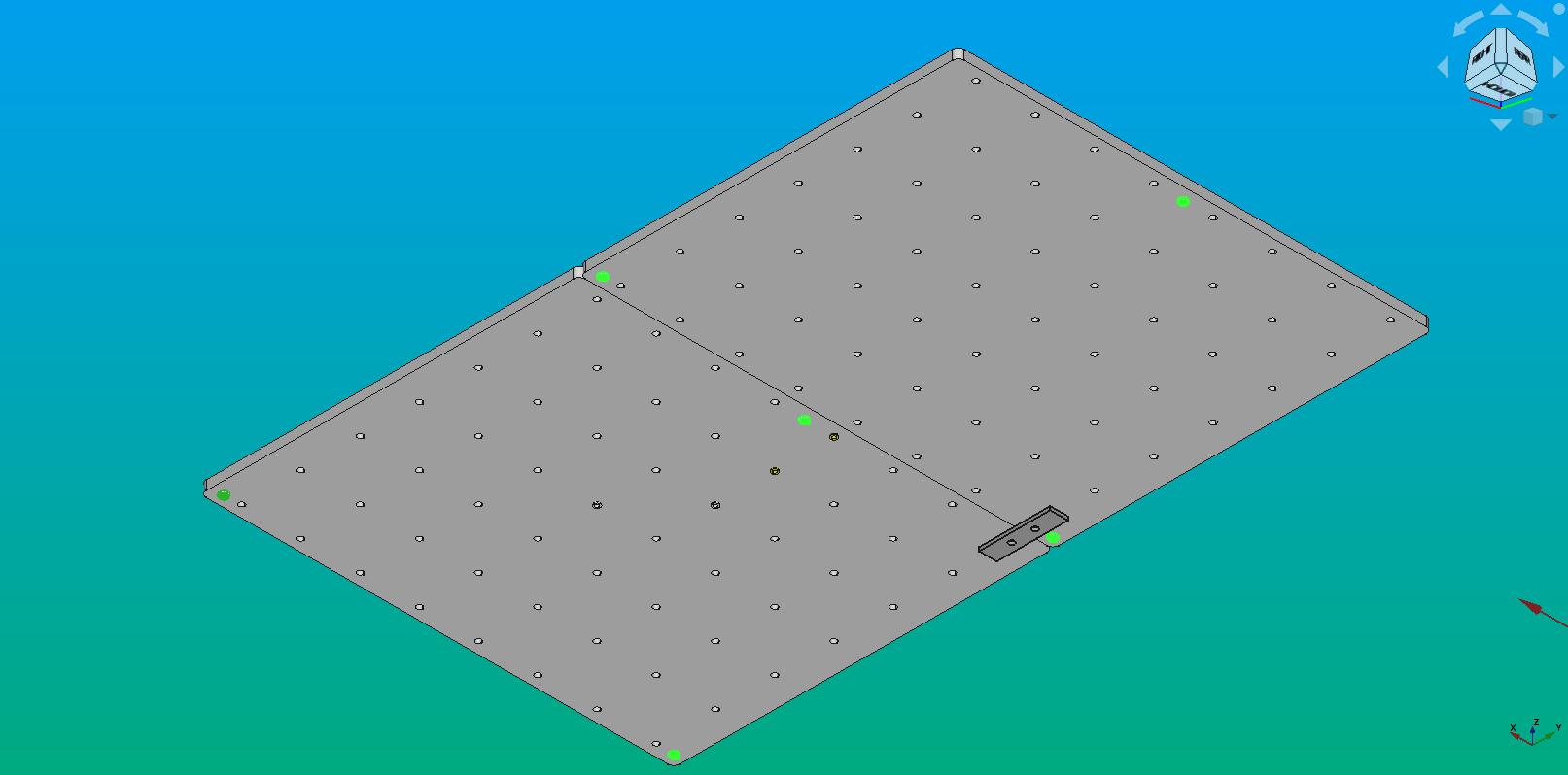
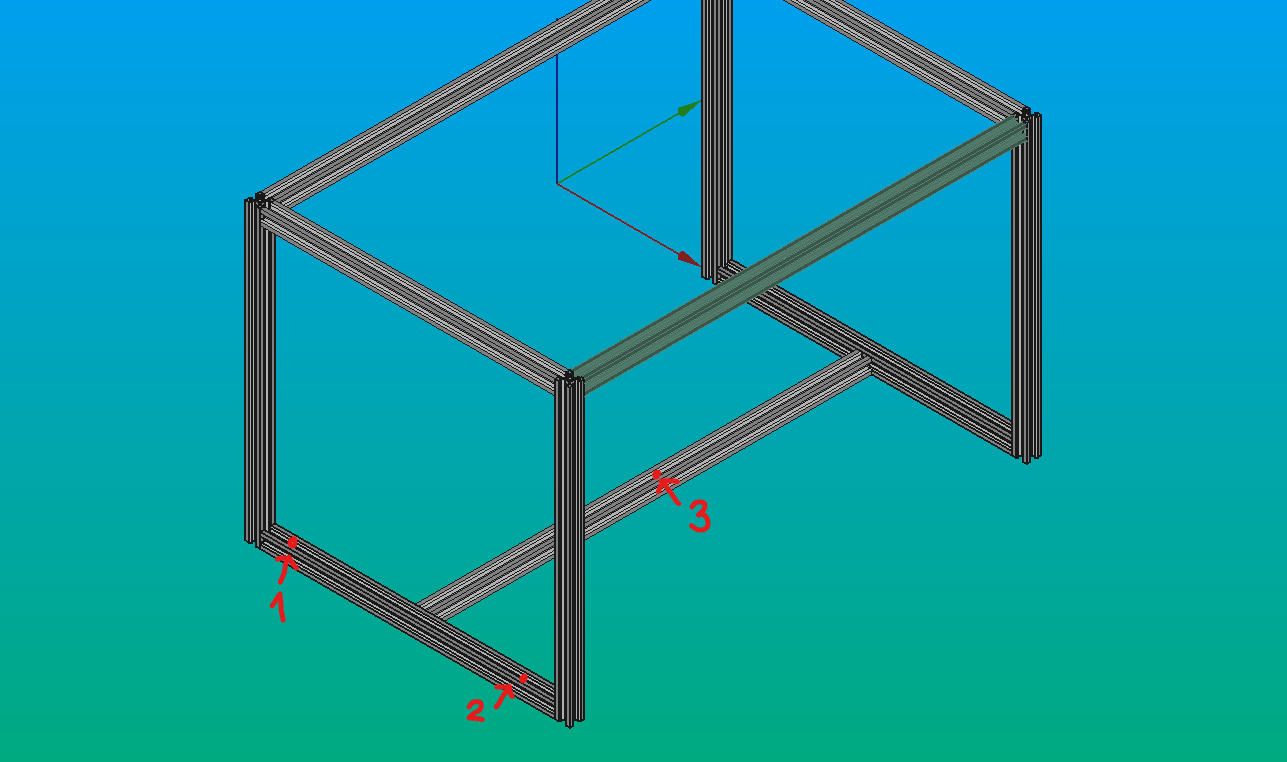
- Add the round-head M4 screws to the holes (red arrows and numbers) using the screwdriver.
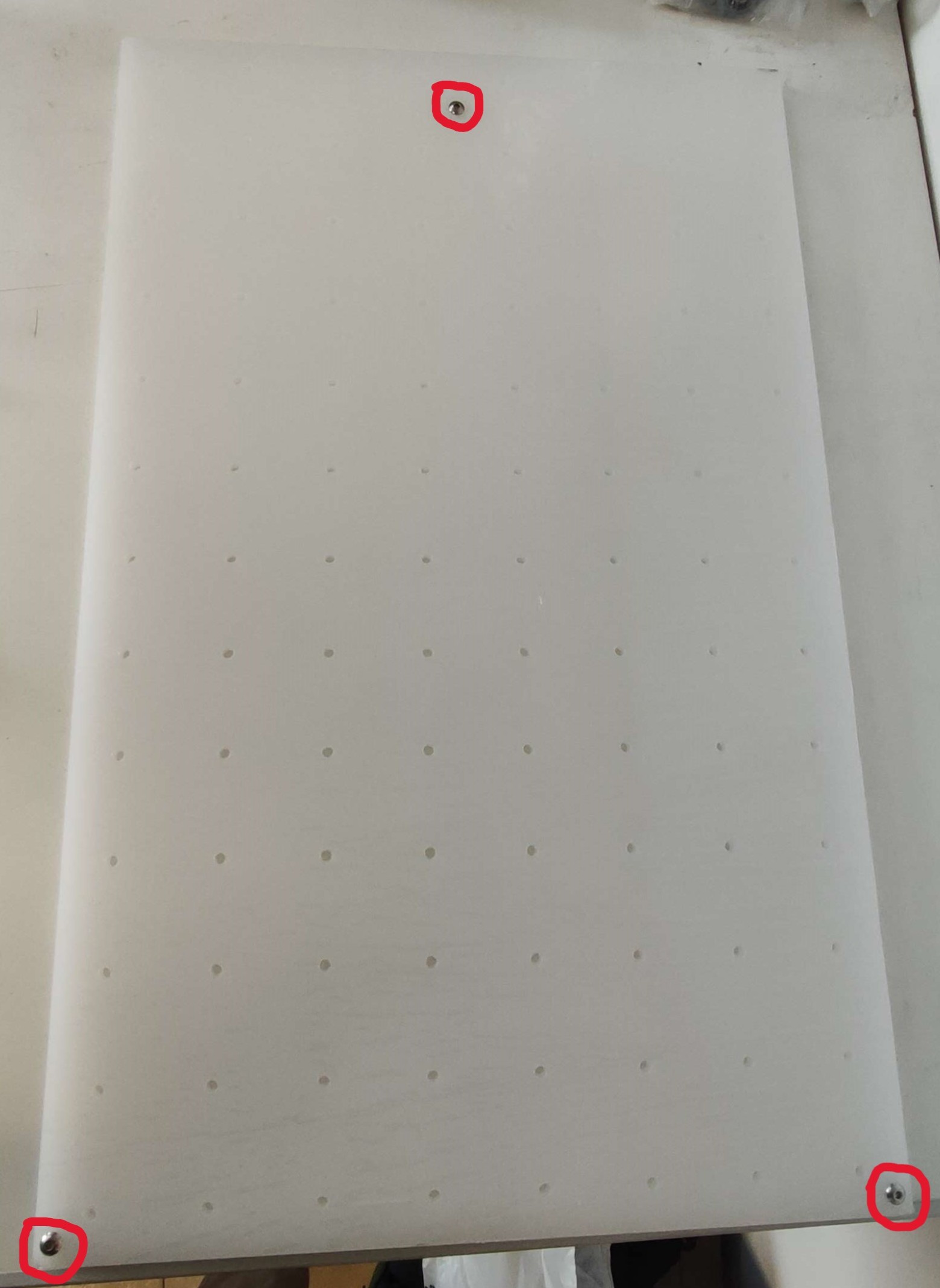
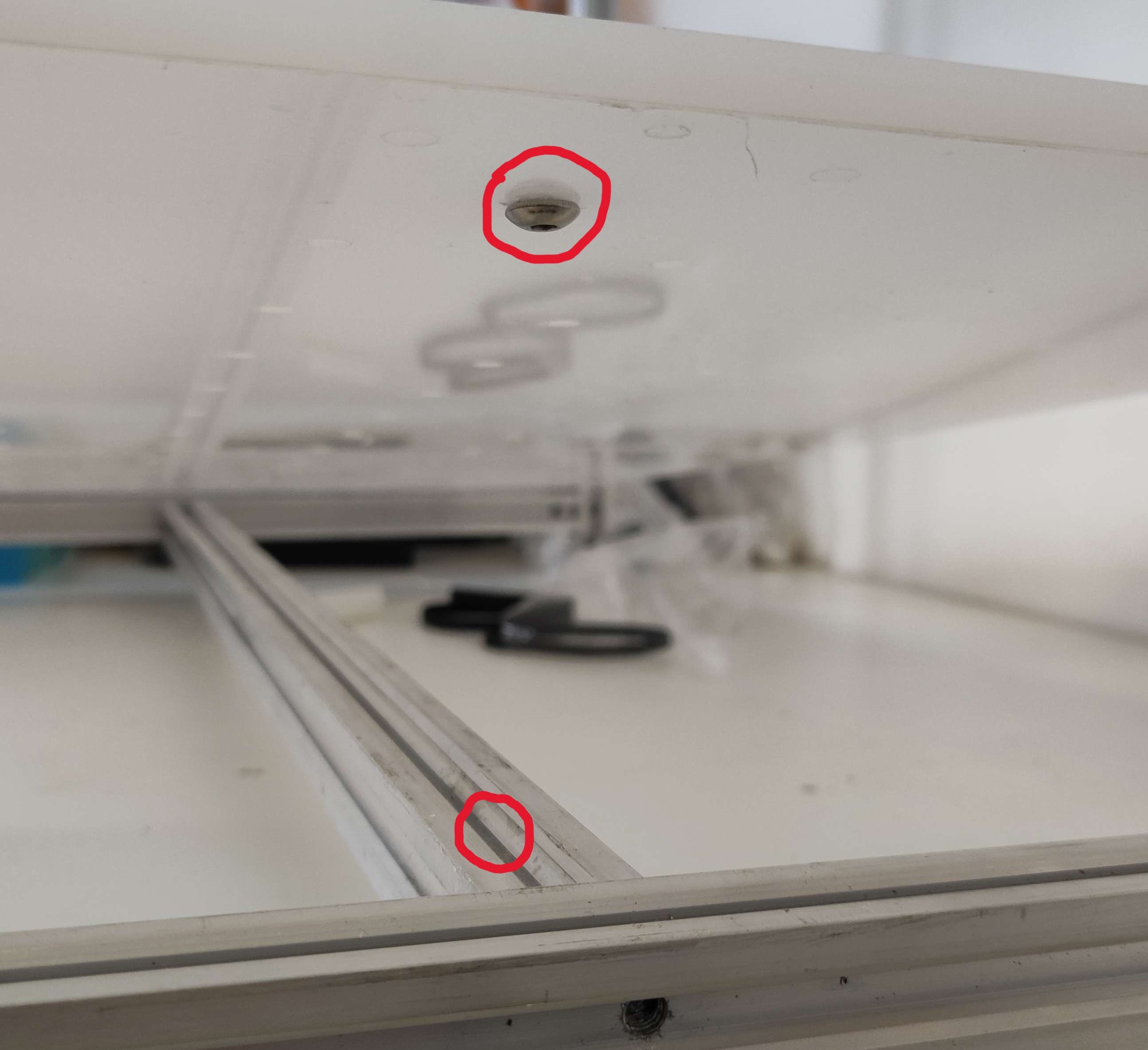
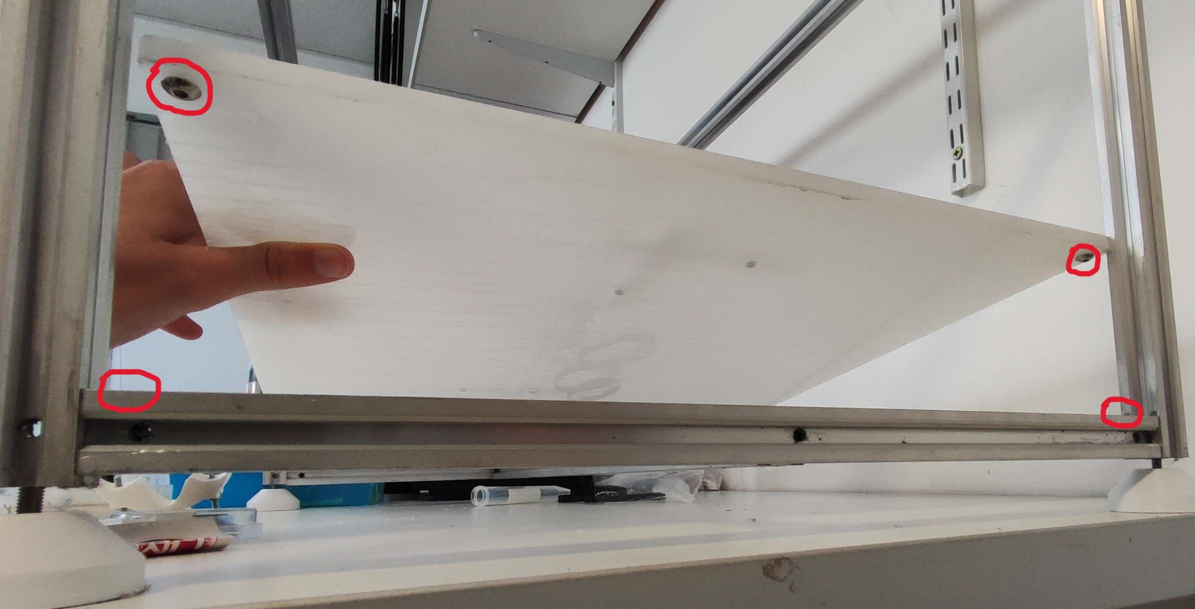
- Place the baseplate on top of the frame. The screws must match their v-slots on their respective profiles (green arrows). Once placed, the baseplate should stay in place with no movement.
- Adjust the screws to ensure that the distance between the baseplate and the aluminum profiles is very small but visible (e.g. ~0.3 mm).
Once placed, the baseplate must have no play in the horizontal plane, and must not be able to tilt. You could check it using a bubble level and touching the baseplate trying to move it. If it doesn't move, it's okay. If it's moves, you have to adjust the screws until the right position.
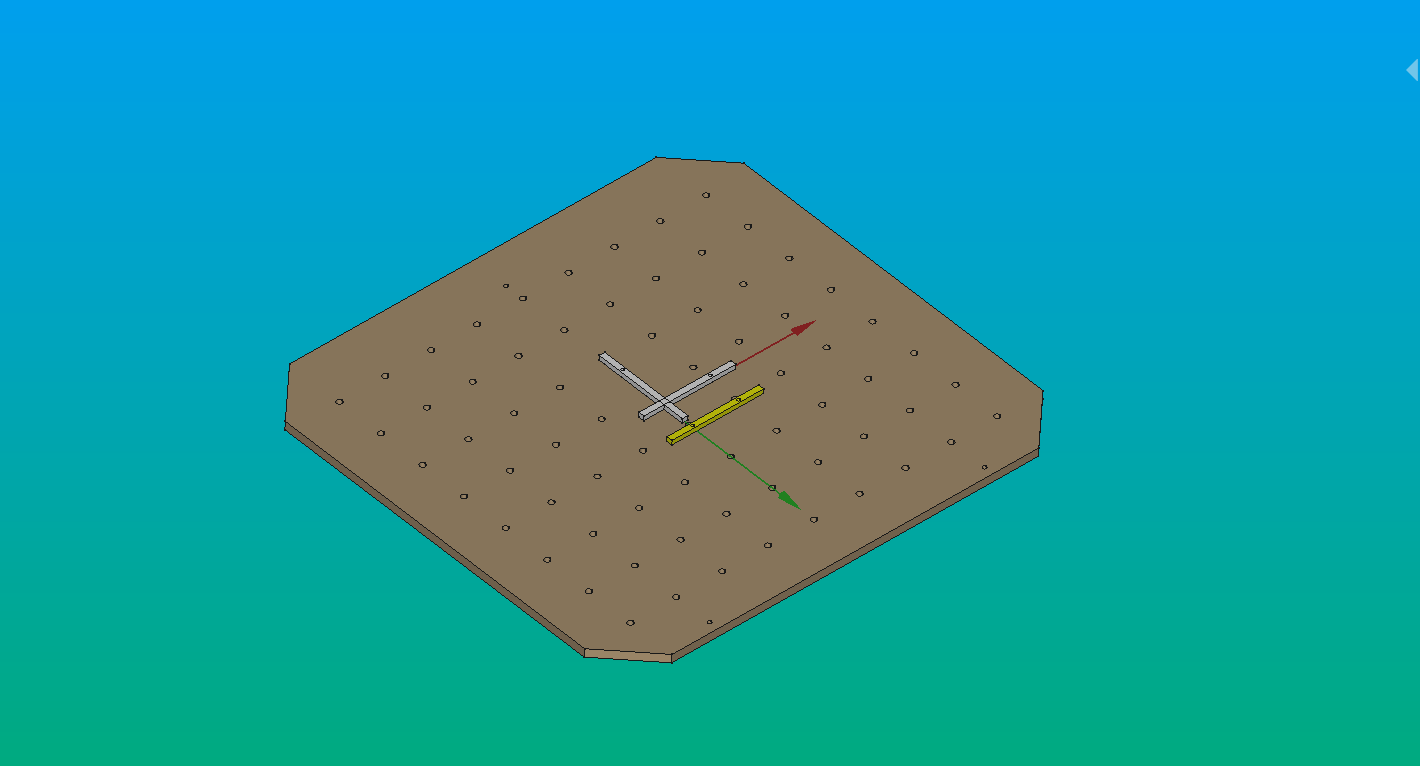
Step 4: Add the curbs
To mount the different types of platforms, you need to use curb. Curb modules are placed as a guide to the platforms on your workspace. Those guides are used to align objects relative to the machine's coordinates, both easily and consistently.
- Place the curbs in a suitable pattern.
- Place some objects against the corners formed by the curbs (red segments).
Info
Calibrations can be done without curbs. However, it might be difficult and it can result in location errors during the process.
It's important to keep in mind that the instructions may vary depending on the type of laser machine and the control software used. Always you have to follow the manufacturer's instructions and check the user's manual.
Step 5: Couple the two halfs
Note
This step is not required for the wood and acrylic baseplates, as they can be cut on a large laser cutter with ease (which is more commonly found than an equally large CNC router).
Warning
Experimental.
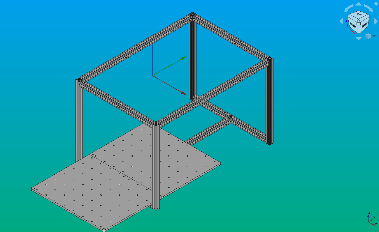
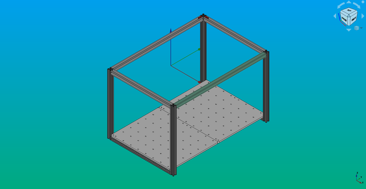
- Place both halfs of the aluminium baseplate on the structural frame.
- Align and level both halfs.
- Use two flat plates to bind the halfs together.
- Because there are now 12 contact points for the baseplate, it is over-constrained. Check for any tilt by pressing on the baseplate on different points. There should be no play at all, otherwise go back to steps 1 to 3.
Interactions
As mentioned previously, the baseplate interacts with the profile’s structure, holding the different platforms. Because of that, it is important to revise the malleability of the materials in use, in addition to the tolerance when drilling it, to avoid problems while calibrating Pipettin.
Besides, depending on it's usage, it is important to keep in mind the interaction between this plate and the chemical substances that are used.
Maintenance
Daily Maintenance
Clean the baseplate.
Long-term Maintenance
Check on the button-head screws of the kinematic system under the baseplate, they should be tight to avoid losing precision.
Replace any platforma nchors/curbs that have become loosely fit to the holes on the baseplate.
The frequency of these actions depends on the use of the equipment.
Design
Chosen materials
-
The first version of the baseplate was a perforated piece of plywood, machined 9 mm thickness, burnished for water resistance. Laminated wood is not super smooth, but it is cheap and gets the job done.
-
The current version of the baseplate is a perforated piece of Aluminum 6061-T6, machined 8 mm thickness. This material is more resistant than wood, and it is also relatively lightweight. It resists corrosion well, and has good weldability and machinability. But the main reason to choose it is the easy anodized, to protect the aluminum against abrasion and corrosion.
-
A third option could be to laser cut plywood (a hardwood such as guatambu) covering it with epoxy resin. It is more resistant than the laminated wood, and the epoxy resin gives it properties such as great mechanical and chemical resistance, electric isolation, and great high temperatures resistance.
-
Finally, other option could be to laser cut acrylic (PET: polyethylene terephthalate). It has high impact resistance. To avoid buckling, it must be quite thick, at least 10 mm. It is also flammable, and does not resist many chemicals.
Design choices
-
We use two baseplates at the same time since it's easier to handle them. And using smaller parts means that they can be machined in smaller CNC mills. It is important that the plates are flat in order to be able to easily gauge the position of the objects, but it is not essential.
-
We made a hole matrix to put different curbs simultaneously, in order to place the platforms easily, with repeatable precision.
-
We put three screws making a triangle in each baseplate, to restrict the degrees of freedom (screws in green in the picture). It locates one rigid body (the baseplate) relative to another (the profiles structure) with very high repeatability, without over-constraining the body or introducing instability. It is based on the Kinematic Constraint principle.
Learning resources:
- Aluminum anodizing: https://aluminium-guide.com/en/anodirovanie-alyuminiya/
- The Principle of Kinematic Constraint: https://practicalprecision.com/kinematic-constraint/
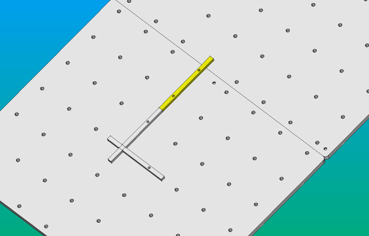
Curbs
Using a regularly spaced, square grid of 6 mm holes, "curb" modules are placed to generate guides on the workspace. Those guides can be used to align objects relative to the machine's coordinates, both easily and consistently.
Modules: two modules are shown, they can be combined to make larger guides.
Frame-mount
A simple but effective 3-point kinematic coupling was used.
The baseplate will sit on the aluminum frame, through the heads of three "round head" screws, placed on the bottom side of the baseplate (see pictures below).
The screws could eventually be used to level the baseplate.
Since the aluminum frame is v-slotted, this system is a "Maxwell" kinematic coupling with 6 contact points (which means that it can only fit in one position and with one orientation, its movement is totally constrained over the horizontal plane).
Three M5, round-headed, Philips screws were placed on the marked holes, "from below" (such that the head of the screws lies on the bottom side of the baseplate).
The three screws on the underside of the baseplate rest on the v-slots of the marked aluminum profiles. Because two of the contact points are on the same v-slot (and thus are parallel), the third contact point can always be aligned with the third screw.
Models
Links to CAD files listed in the sources page.
Development
These 3D-printed parts were designed in FreeCAD 1.0, and saved in the native FCStd format. Printable STL files were printed on an Original Prusa i3 MK3.
To learn more about these file formats visit here.