Backpanel
Backpanel
Info
Discord forum thread: Electronic case
Overview
The back-panel serves as the structural foundation for the Pipettin bot's electronic components. Composed of acrylic, this panel provides a platform for mounting electronics parts.
Throughout this section you will find general guidelines for building the Pipettin bot's back-panel and attaching different components to it.
Usage
Once the back-panel is properly attached to the structural frame, you may use it to mount the electronics and tool posts.
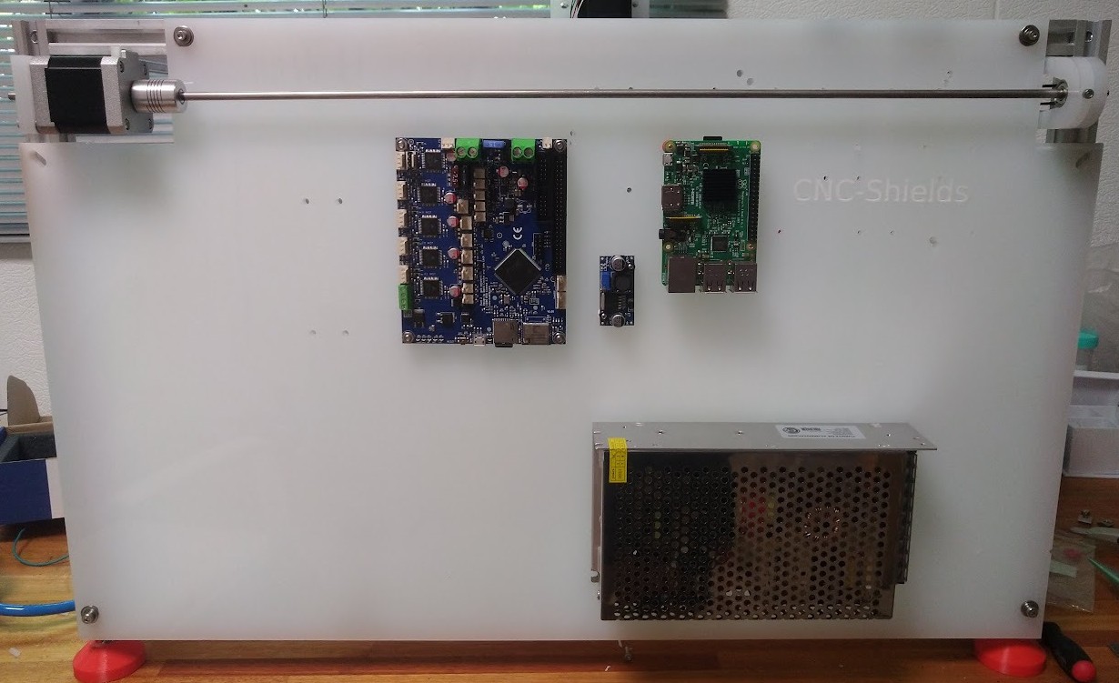
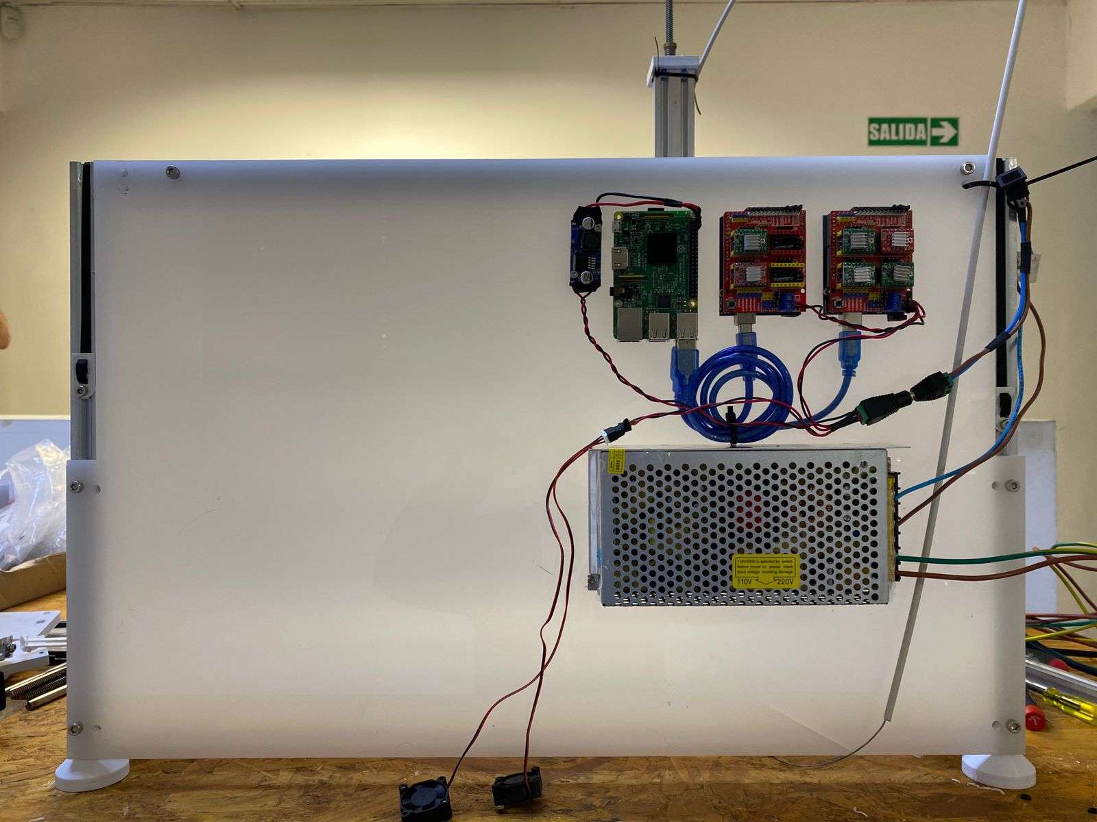
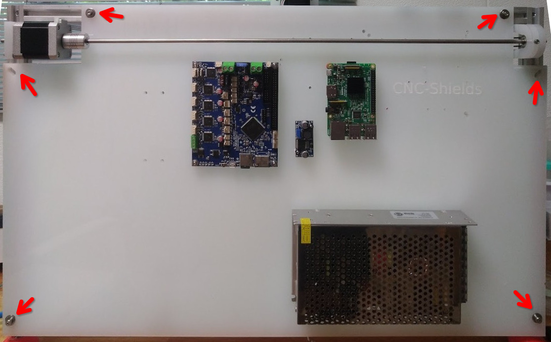
The images below present layouts for the two sets of electronics we have tested:
Assembly
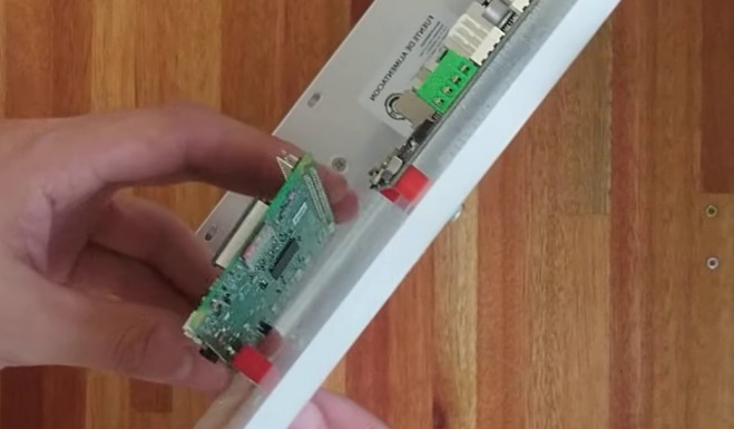
Before connecting cables, you must mount the backpanel to the "back" of the structure. You also ensure that the back-panel is aligned and properly fastened to the structure, using screws and T-nuts.
Stepwise guide
A nice and updated step-by-step guide for the assembly is available:
Instructions below can be considered development notes.
Manufacturing
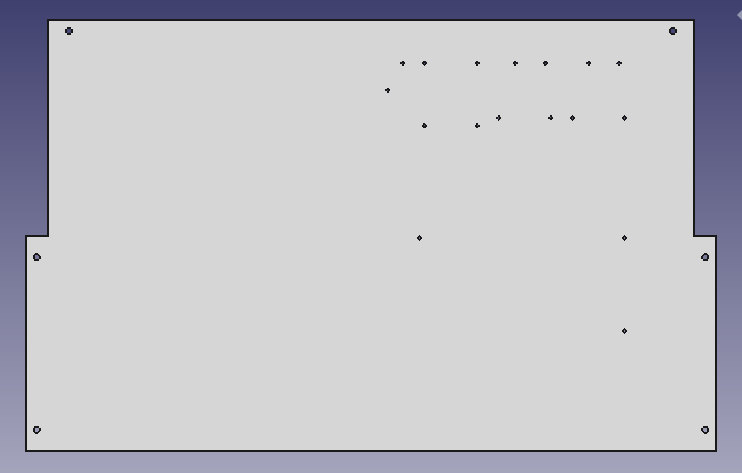
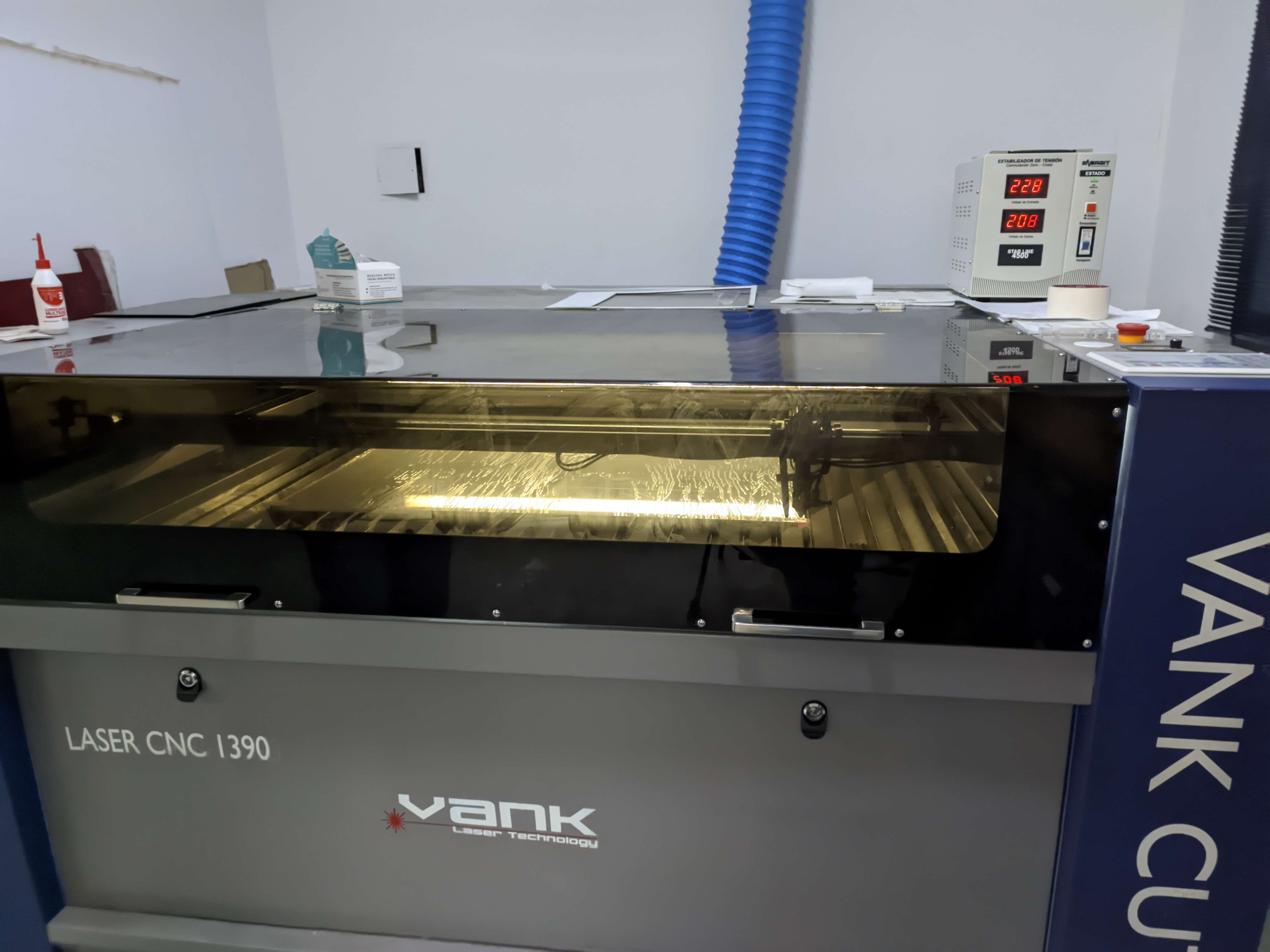
Step 1: Laser cutting
If you have access to a Laser CNC, you should set it up first:
- Load the design file into the Laser CNC software (in our case, LightBurn Beta 0.8.07).
- Set maximum speeds and laser power. This was 100% at 7 mm/s for 8 mm thick white acrylic.
- Load the cutting program and then cut the piece.
Step 2: Gather parts
Gather parts listed in the bill of materials.
Step 3: Mount it to the structure
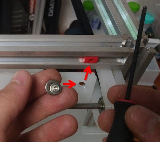
After making the back-panel, place it within the structure and secure it using screws along with their corresponding sliding T-nuts.
Location of the mounting points:
Slide-in nut detail:
Step 4: Drilling mount points
The location of tool-posts is not pre-defined, and will need to drill holes into it later. The same applies to other custom components you may want to add.
To drill additional holes into the back-panel, use a 3 mm drill bit. Remember to set your drill to a low speed and apply moderate pressure while drilling.
Tip
Excessive speed and low force can cause the acrylic to melt on the drill bit, so take your time and let the bit do its job. You can apply some water to act as a coolant just to be safe.
Interactions
The back-panel is mounted on the Structural Frame. It's located at the back, on the external face of the structure, joined by sliding screws and nuts, adding stability to the structure.
The electronics and the tool-changer motor are mounted on the external face of the backpanel, and the tool-parking posts on the internal face of the backpanel.
It is also the a good place to attach parts that needs to be stay mounted in a fixed location (e.g. tool posts).
Arduino, Raspberry Pi, step-down module, and power supply are mounted onto the panel with screws, separators and nuts.
Maintenance
Before doing any operations on the backpanel, shut down and completely disconnect power from the machine.
Some maintenance items to consider:
- The backpanel should be kept free of dust. The fans can be easily removed from the CNC shields for cleaning.
- You may want to check on the temperature of the drivers by touching them (very carefully) and regulate it if they are too hot.
- Have a look at the remote-actuator maintenance section. It is mounted on the backpanel.
Design
The main purpose of this panel is to serve as the support for all the robot's electronics, but it was also designed in this way to provide structural support, it contributes to the overall structural integrity.
We opted for laser-cut acrylic for its ease of fabrication, but alternative materials like hand-drilled acrylic, wooden sheets, or aluminum bars could also be considered.
Models
Links to CAD files listed in the sources page.
Development
These 3D-printed parts were designed in FreeCAD 1.0, and saved in the native FCStd format. Printable STL files were printed on an Original Prusa i3 MK3.
To learn more about these file formats visit here.