Electronics
Electronics for the Pipettin Bot
Tip
Ask for help on the Discord: Pipettin Bot Electronics
Overview
This section aims to provide comprehensive guidance on installing and configuring electronics to control the actuators on the robot.
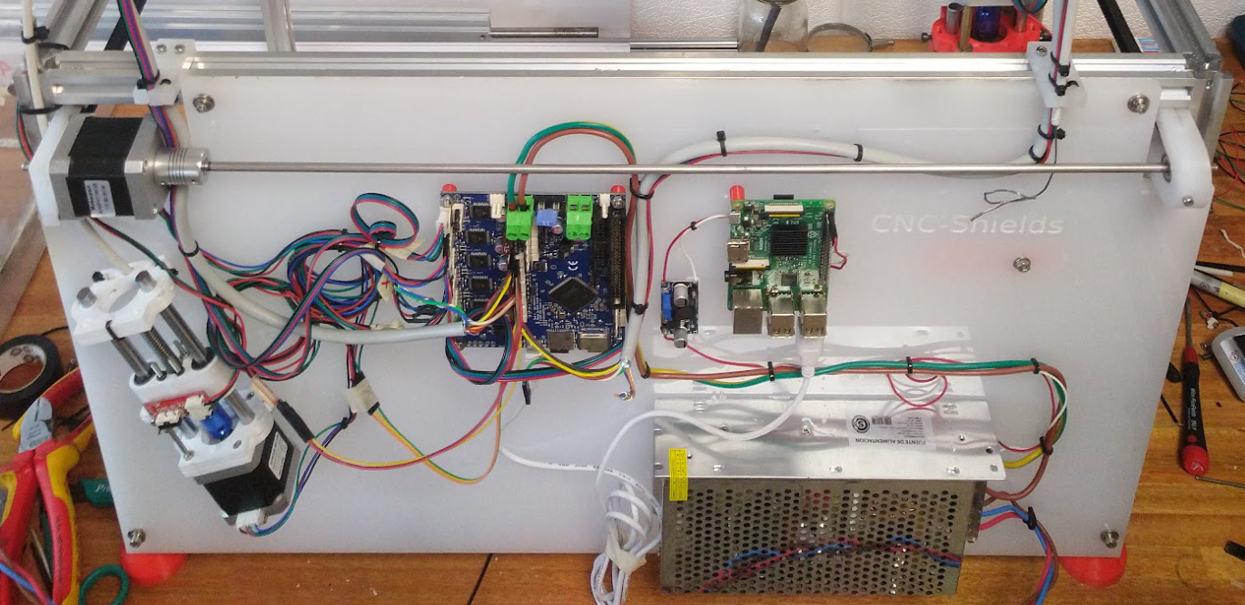
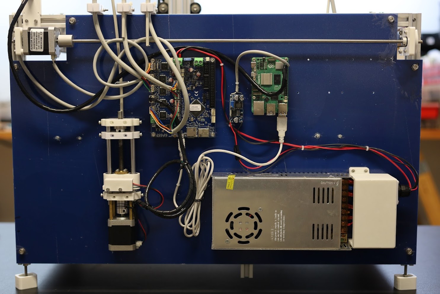
The backpanel is where all the electronics will be mounted. This version is meant to have a RPi model B (left side) and two Arduino UNO with their respective CNC shields mounted on top of them (center and right side), and has mounting holes for a Duet2 WiFi as well.
The sides are slotted for M3/M4 screws, used to secure it to the 2020 profiles of the frame, using matching drop-in nuts.
Expected result:
How different versions look like
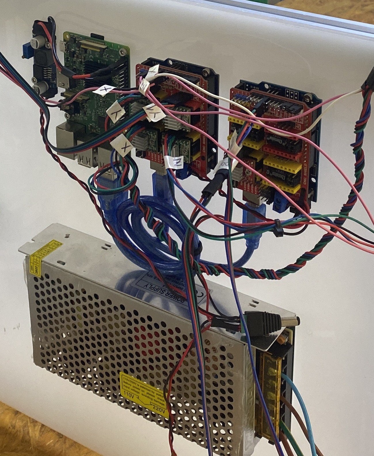
The images show possible layouts for either the Duet2 WiFi, or a pair of CNC-shield V3.0 controllers. There may be additional electronics mounted on the robot's tools, axes, or baseplate.
Electronics mounted on the backpanel: Arduino UNO + CNC shield operate the XYZ and tool-changer remote axis of the CNC machine. Another Arduino UNO + CNC shield with controls up to 4 tools.
These Arduinos are controled directly from the Pi's USB ports. A step-down module powers the RPi through it's GPIO header. The main power supply can provide 10A at 24V.
Usage
The electronics are meant to be operated through graphical user interfaces, enabling users to send commands, configure parameters, and monitor the robot's operation.
There are a few control interfaces for the user:
- The Pipettin Writer GUI, a specialized web interface for programming liquid handling protocols.
- The "joystick" (i.e. Mainsail's web interface), a simple interface for manually controlling and calibrating the robot's movement.
- The robot can also be operated using PLR, through a JupyterLab notebook (WIP).
These applications run on a Raspberry Pi, which functions as the robot's main computer (although any Linux PC can be used). It serves the user interfaces and translates incoming instructions into executable GCODE commands. These commands are then relayed to the CNC boards, which in turn drive the stepper motors.
The CNC boards are responsible for the precise control of the stepper motors, essential for the accurate and controlled movement of the robot.
Assembly
This documentation provides step-by-step instructions to facilitate the study and replication of the robot's electronics, ensuring an open and accessible platform for users to make and modify the system according to their specific requirements.
Disclaimer
Instructions below may involve mains power, which is extremely dangerous.
We assume no responsibility and are not liable for any equipment damage or physical harm produced by the use of these instructions, which are given as-is, and with no guarantee in accuracy or safety.
Briefly, throughout this stage you will:
- Make a case for the main PSU.
- Install all electronics on the backpanel.
- Mount endstops, wire motors, and cooling fans.
- Connect the Rapsberry Pi to the CNC boards.
- Manage cables.
The assembly instructions for the electronics are split into a few StepWiseDocs guides:
Overview of the end result:
Interactions
The electronics are mounted directly on the backpanel with screws, and are connected to all stepper motors, endstops, pipettes and tools through cables.
Briefly, the electronics are connected as follows:
- Power connections between the PSU and the Raspberry Pi, and the CNC boards (e.g. Duet2 WiFi or CNC shield).
- Data connections between the Raspberry Pi and the CNC boards, and the mini OLED display.
- Control connections between the CNC boards and the stepper motors, endstops (limit-switches), and electronics mounted on tools (e.g. pipettes).
These connections are summarized in this SVG diagram, which you can open using Inkscape. Open the diagram with Inkscape, and toggle the visibility of the different layers to switch between visualizations of data and power connections.
Data connections example (Duet2)
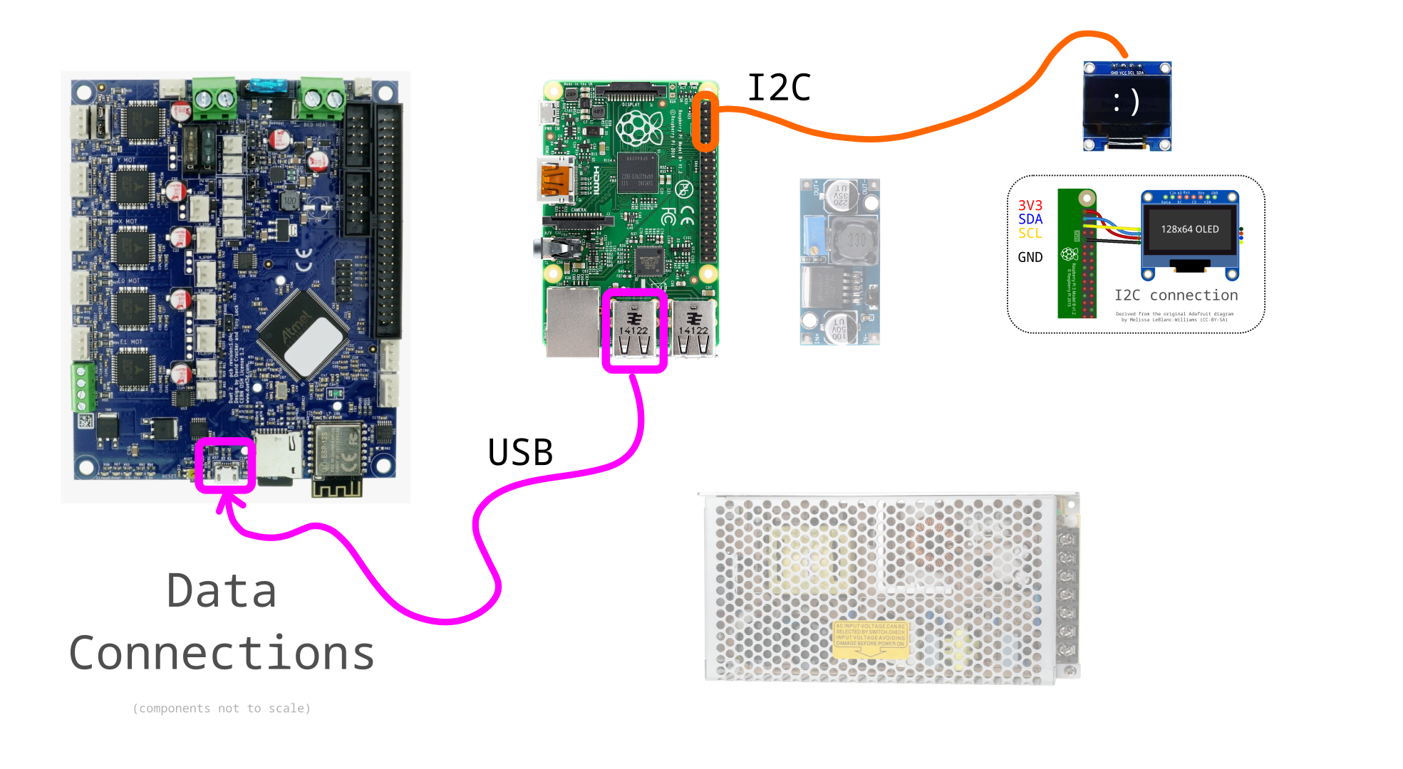
Note that connectors for limit switches vary between boards. Duet2 boards use 3 wires with VCC in the center, while the CNC-shield has GND at that position, or may use only 2 wires (omitting VCC).

Maintenance
In all cases, disconnect power before doing any maintenance on the electronics.
Dust will accumulate on the electronics, which may cause issues if unattended. Check for accumulation of dust and signs of corrosion regularly.
It may also be a good idea to snif around the electronics too, looking for any strange smell coming out of it.
If a particular stepper seems to be malfunctioning, try replacing the corresponding stepper driver.
Design
The electronic components were not designed by us, but we chose them according to their openness and ubiquity.
For example, the Raspberry Pi, Arduino UNO, CNC-Shield v3.0, and Duet boards are all open source hardware designs.
Most of these are also ubiquitous, except for the RPi and the Duet, which are easily replaced by a Linux PC and Arduinos, respectively.
Power Supply
The main power supply should output 24V and at least 8A.
The Pi is powered directly through its GPIO header, through a step-down converter that can deliver at least 3A at 5V.
A wiring diagram is shown below, pay close attention to which pins need to be used.
There is also a guide by The Pi Hut, with a section describing this in more detail: https://thepihut.com/blogs/raspberry-pi-tutorials/how-do-i-power-my-raspberry-pi

A step-down "buck" converter is a DC-DC transformer device that converts a higher input voltage to a lower output voltage. The output voltage is always lower than the input voltage, regardless of changes in the input voltage or output load.
In the case of a Raspberry Pi, the DC-DC converter step-down is used to convert a 24V input voltage to a 5V output voltage. This is necessary because the Raspberry Pi can only be powered by a 5V supply. If the Raspberry Pi were to be powered by a 24V supply, it would be damaged.
The DC-DC converter step-down is a simple device, but it is essential for protecting the Raspberry Pi from damage.
Limitations
Incorporating additional tools or accessories beyond the standard pipette, such as a hot bed, laser module, or similar devices, may necessitate modifications to other system components to ensure optimal functionality and maintain system integrity. One critical aspect to consider may be the power supply unit, for example.
The cheaper stepper motor drivers (e.g. A4988 and DRV8825) are more prone to failure. Such issues might arise when the "Vref" (reference voltage) isn't adequately set to supply optimal current to the stepper motors. You'll find instructions for this in the electronics setup guide. Even if respecting their maximum ratings, these drivers are a hit or miss: most of them will be good, but a few of them will fail too soon.
The Duet2 WiFi can only control 5 motors. This means that a Duet-only setup will be able to use a single micropipette tool. There is an expansion board which we have not tested with Klipper (which does not recommend using the "multiplexed" IO pins to drive steppers or sense endstops). Consider adding a CNC shield to this setup instead, in order to drive more tools.
Models
The only models used for the electronics are those corresponding to the "backpanel" in charge of supporting the electronics. You can find them by clicking here.
Software
Find everything you need to know about pipettin software at Software Setup Guide.
Development
The Backpanel was designed in FreeCAD, then cut in a laser CNC (cutting program: LightBurn Beta 0.8.07).
To learn more about these file formats visit here.
Congrats!
By completing these steps you have wired and cable-managed the electronics of the robot.
You may return to the assembly guide to continue: Assembly Guide.