FreeCAD How-to Guide
Modeling in FreeCAD
App Settings
To model in FreeCAD, we use the parameters shown in the images below

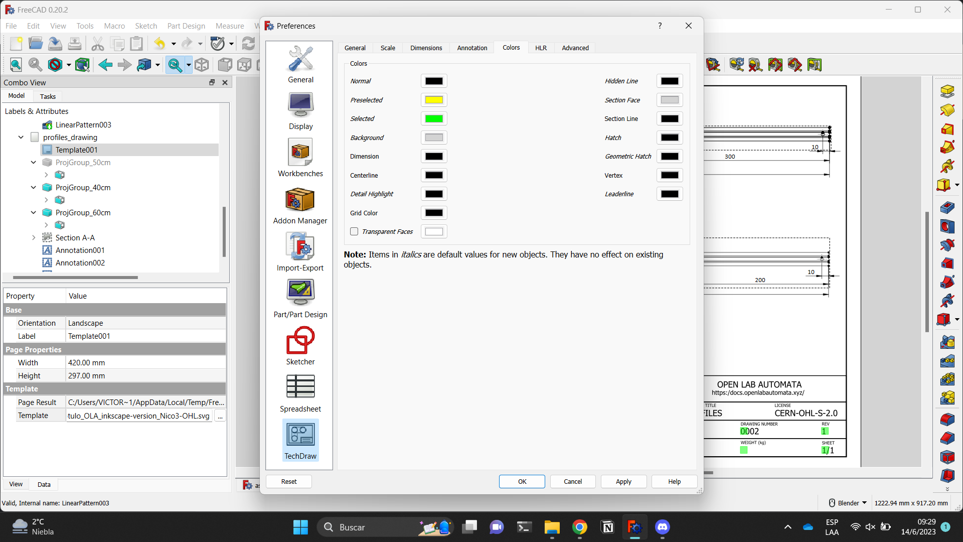
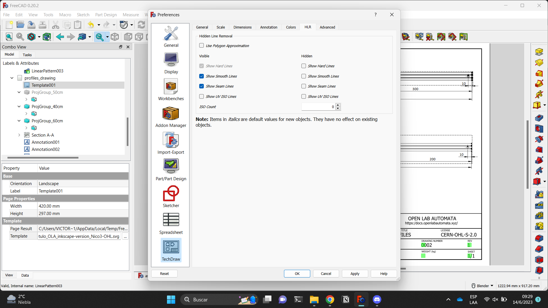
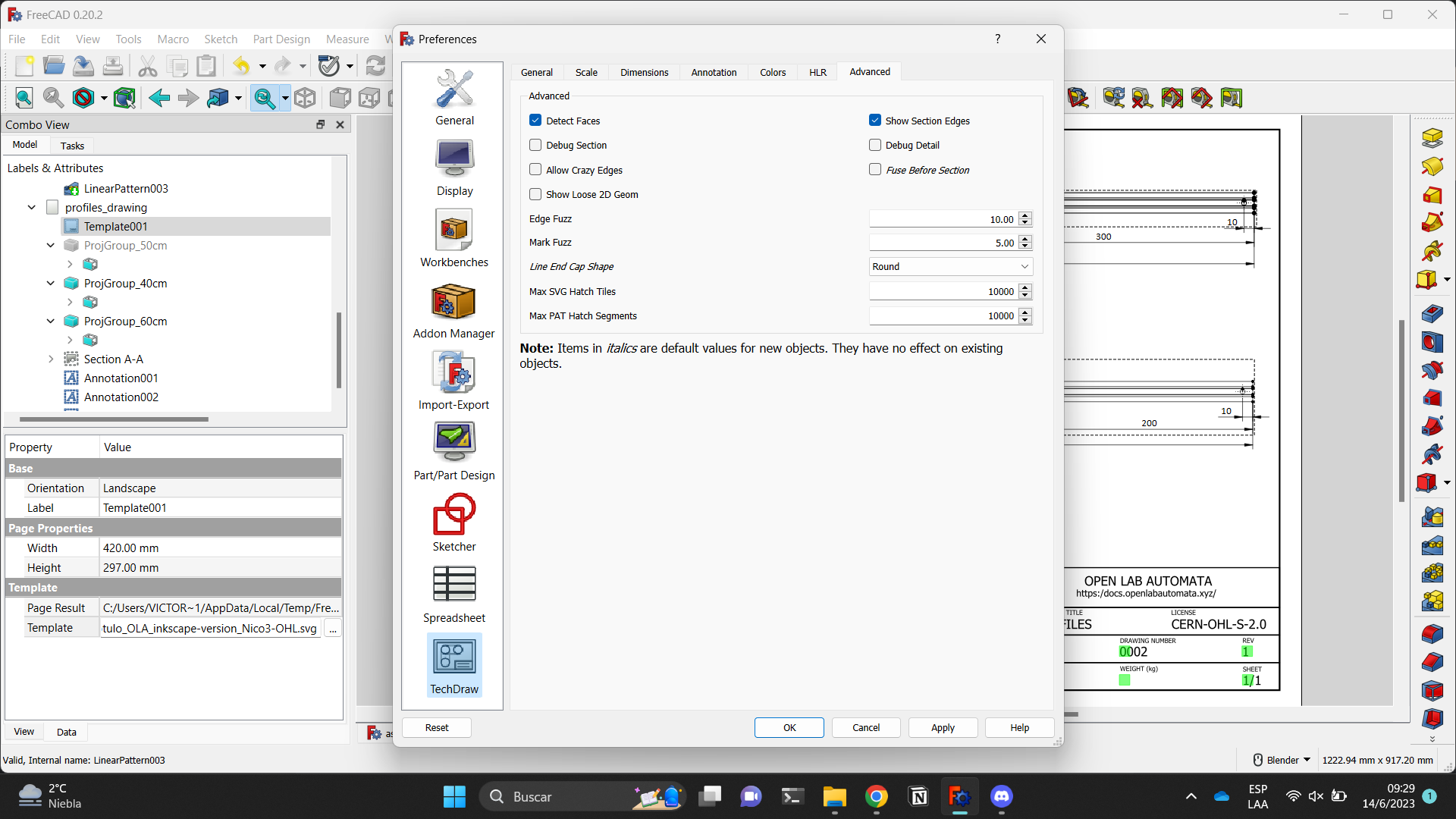
We use the Part Design plugin (red), with which we can use the 'Create Sketch' tool (blue) to generate a sketch. Subsequently, we can perform various actions on the sketch, such as extrusions, fillets, and pockets, among other things (green).

How to download .FCStd files
If you want to access a specific model of Pipettin Bot's mechanics for viewing and modification, the first step is to download the .FCStd file/s.
All models live in the main GitLab repository, and instructions to download all models are in it's README file.
Many of the files include parts from other files by linking. We recommend downloading the whole thing to avoid confusion.
Info
To open a .FCStd file, you must have FreeCAD installed on your computer.
Here you can find information regarding which version of the program we use.
Here you can download the software by following the instructions, according to your specific OS.
Download instructions
The recommended way to download the models is to clone the GitLab Repository, and checkout the CAD files with git lfs.
Info
There is no need for you to register or have an account on Gitlab in order to download these files.
Run the following commands in a terminal (git and git-lfs are required):
# Clone the repository.
git clone --singe-branch -b master --depth 1 https://gitlab.com/open-la/pipettin-bot.git

# Activate git LFS, and download the CAD files.
git lfs install
git lfs pull

# Enter the models directory.
cd pipettin-bot/models
If this is too technical for you, you can also download the models from the GitLab Repository of Pipettin Bot.
Linked models and Assemblies
If you want to properly open a model that imports other models, you should download the whole repository using git (as explained above).
Otherwise, FreeCAD will not be able to open the missing linked models, which will fail to appear.
Step 1. Use a browser to access the GitLab Repository of Pipettin Bot and click on the "models" folder.
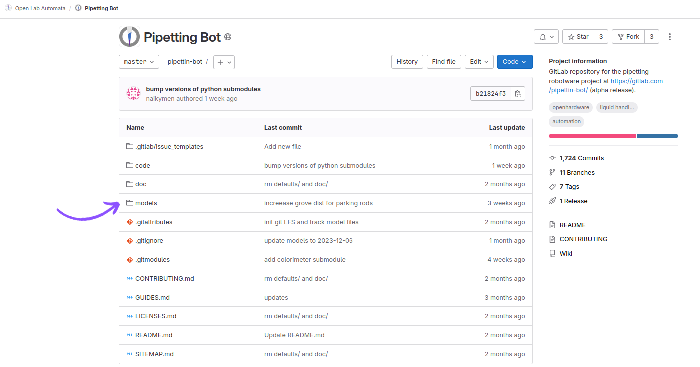
Step 2. Browse the folder to find the file you want to download.
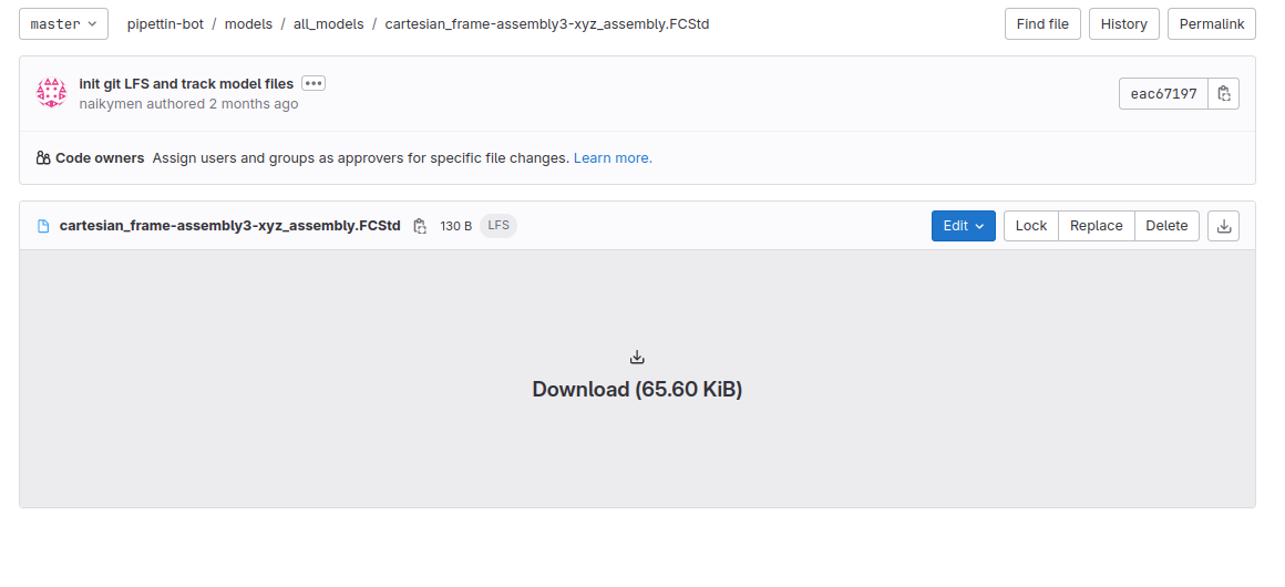
Step 3. Finally click on "download".
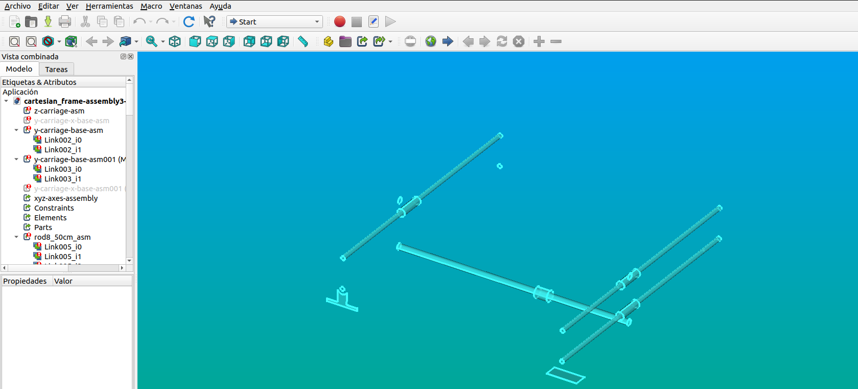
Step 4. Once you download the file you should be able to open it in FreeCAD.
How to modify .FCStd files
First, you need to open the file in FreeCAD. Then, you will see different tabs on the left-hand side of the screen. In this section called 'Models' you will find the various layers that define each part.
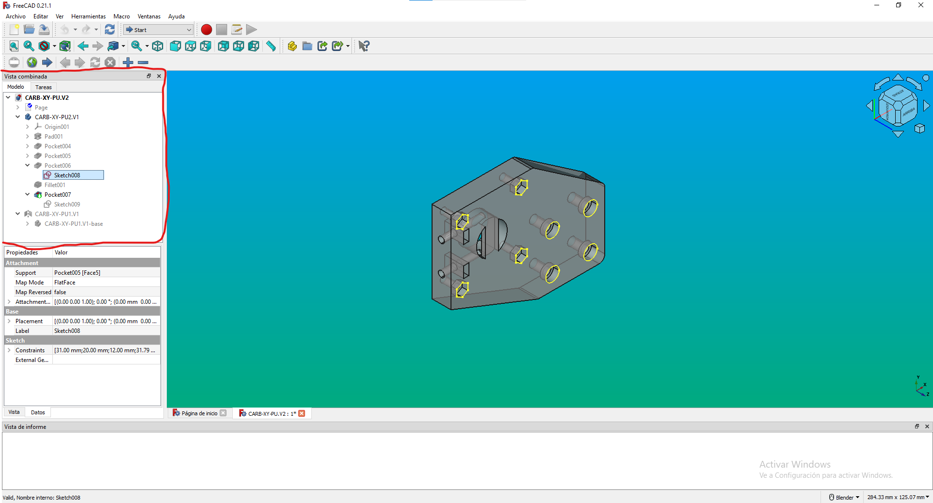
In the image above, the file CARB-XY-PU2.V2.FCStd was opened, which contains two models: CARB-XY-PU2.V1 and CARB-XY-PU1.V1.
The only items with colored names within the file tab are those belonging to the CARB-XY-PU2.V1 model. These include the sketch named "Sketch008" and the action "Pocket007" This implies that only these items will be visible when attempting to view the 3D model.
What is highlighted in yellow in the model is the drawing of the sketch named "Sketch008", which belongs to the action "Pocket006", This allows you to identify the plane used for that specific action.
Additionally, the action "Pocket007" is marked, allowing you to view the model updated to that particular action. It's important to have the tab of the CARB-XY-PU2.V1 model highlighted in color.
Info
If it's not highlighted, no actions or sketches selected for visualization will be visible. To mark or unmark an item for visualization, you can use the space bar.
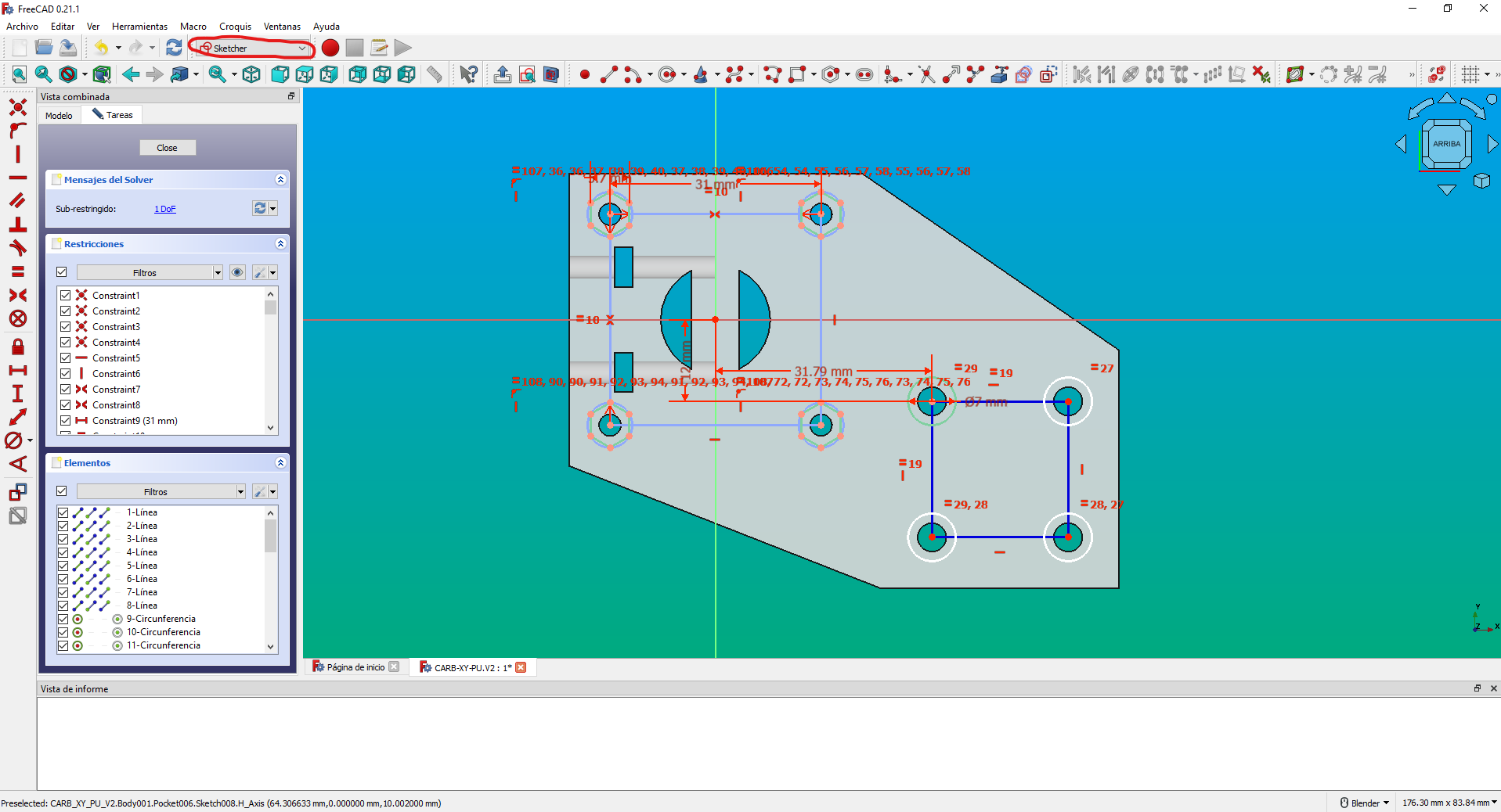
The lines in green are fully constrained, while those in white still have some degree of freedom.
The ones in blue are construction lines with some available degrees of freedom that won't be reflected in the action performed with that sketch.
If the construction lines are in light blue, it means they are already fully constrained. You can edit any of these lines to change the model generated by the corresponding action for the sketch.
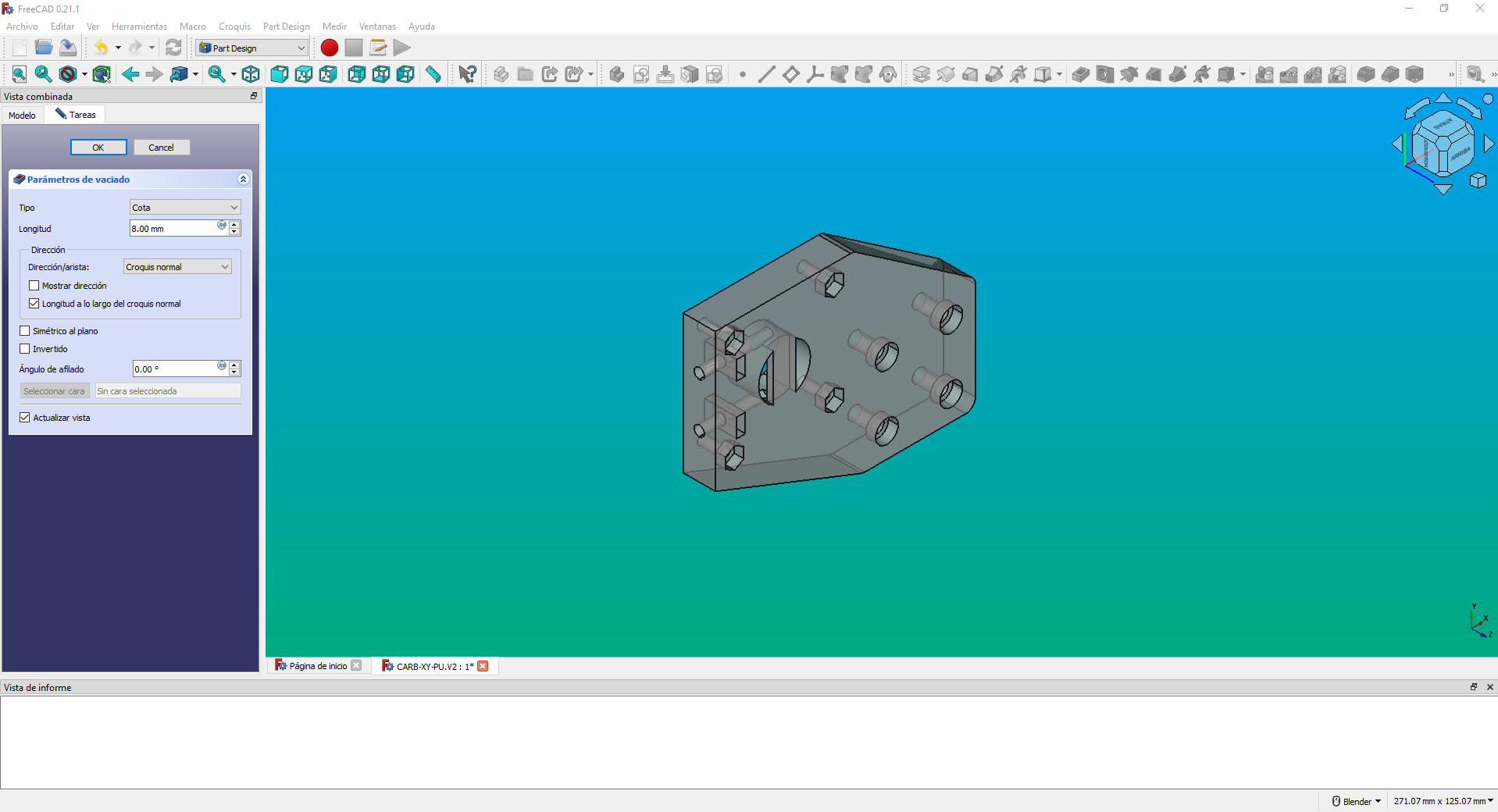
If you double-click on one of the actions, you can observe that it will open the corresponding plugin. In this case, the "Part Design" plugin has opened, corresponding to the action "Pocket007." On the left-hand section, you can see the different parameters for that action.
Info
It's crucial not to delete any action that has subsequent actions dependent on it, as this can lead to the breaking of all the following actions.
With the built-in assembly plugin, you can create assemblies with different parts using constraints.
To create one, click on the "Create Assembly" action, and it will generate a blank assembly. You can add the models you want by dragging them onto the assembly, although we normally use links to parts instead of parts themselves. You can link parts from other files by dragging while holding the Alt key. Just make sure to have the various files you want to use for the assembly open in the program.
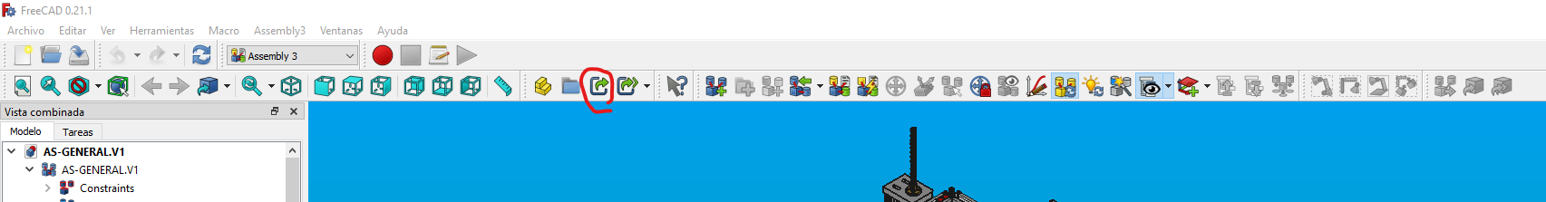
To avoid adding the original model to the assembly file, you can create a link to it and move that new link to the assembly. This can be achieved using the "Create Link" tool, which is highlighted in the image above. By doing this, you can use the same model in different assemblies without the need to copy it into each file. In case you modify the original model, all the links will be updated accordingly.
Preparing Technical Drawings
TechDraw is an add-on for the program that allows us to create plans and technical drawings of the parts we make. To generate the plans in this project, we use the parameters shown at the beginning of this page.
The generated plans are in .PDF format for your viewing convenience. However, if you wish to inspect them in FreeCAD for modifications or similar purposes, you should open the specific part you want to review.
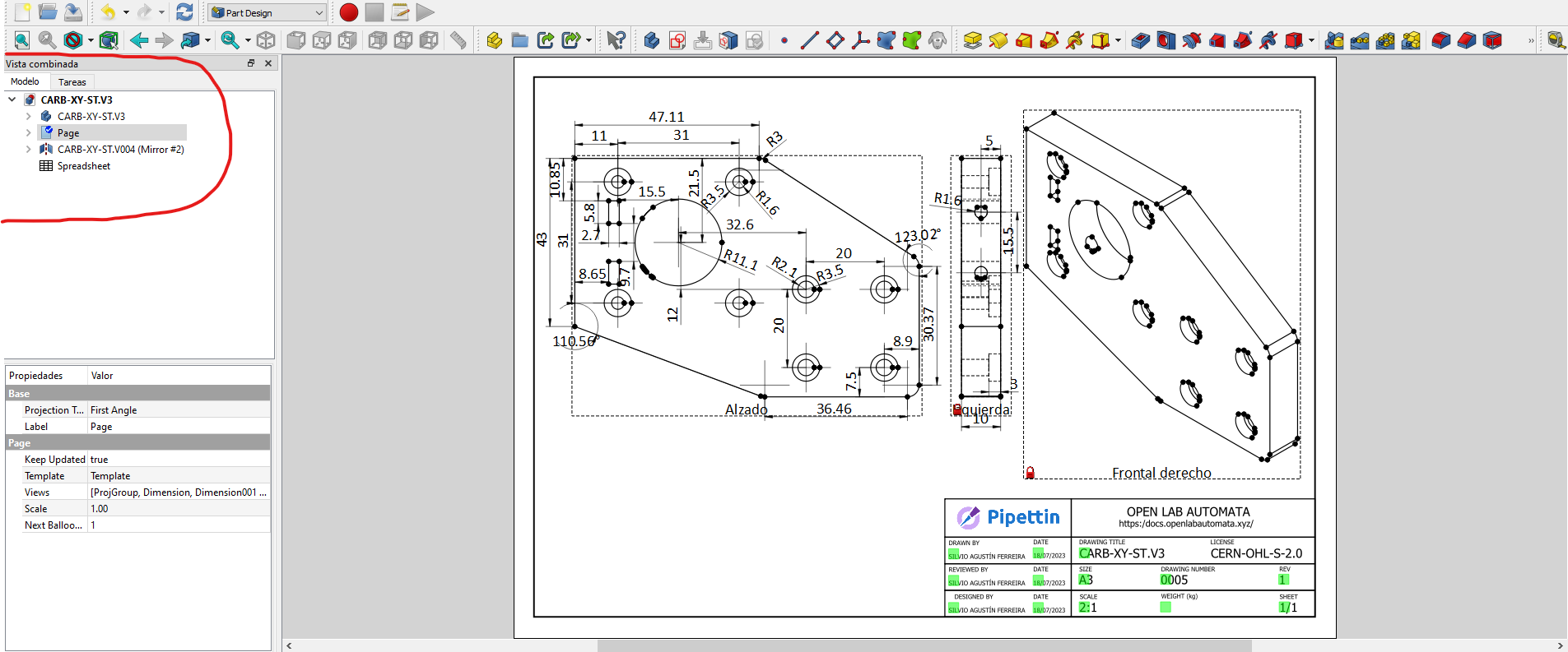
You can access the plan through the left-side window called 'Combined view,' in its 'Models' tab (highlighted in red). The plan will be named 'page.' Once you enter there, you can view the part's plan along with all its dimensions and annotations.
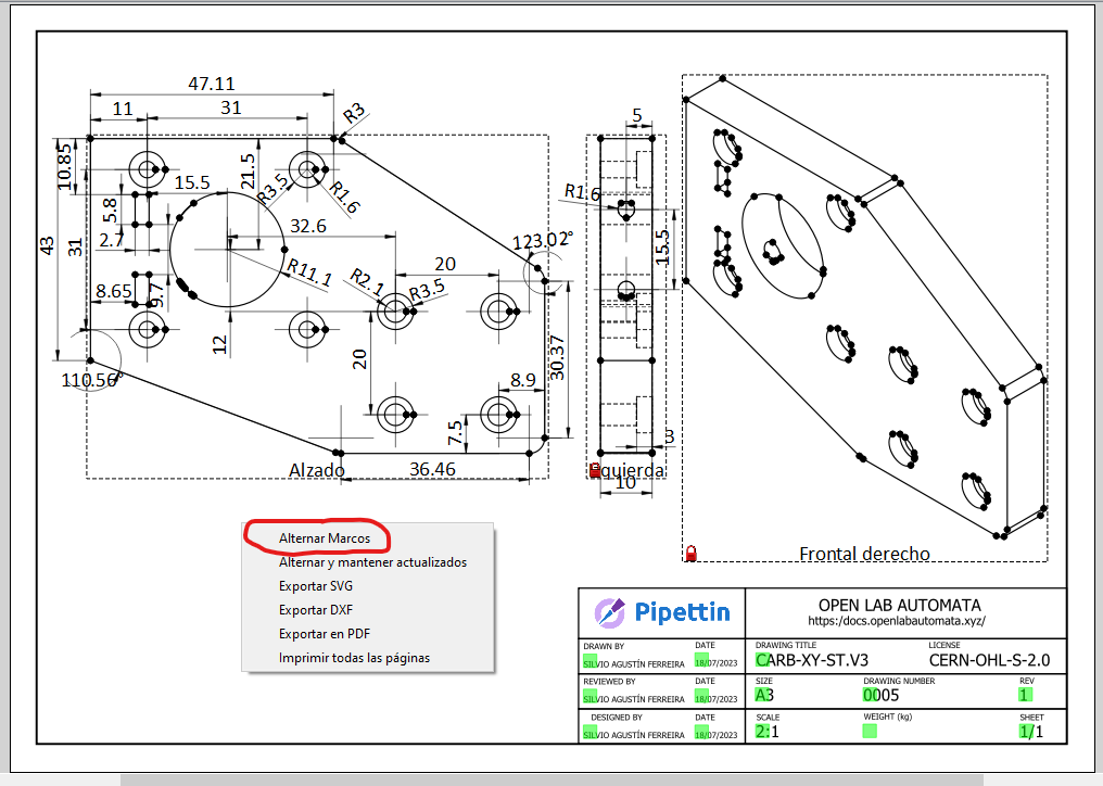
You can show or hide the macros on the plan by right-clicking on it and selecting 'Toggle Macros.
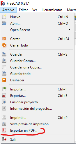
To export it as a .PDF, you should go to the 'File' tab in the upper-left corner and select 'Export as .PDF.
Understanding the BOM
Warning
Our bill of materials (BOM) is not automatically generated, and may be outdated relative to the latest version.
At the bottom of the file you can see the BOM separated by the bot's systems on different pages. On each of these pages you will find the parts and materials necessary to assemble each system.
Info
To learn how we name Pipettin Bot's parts visit Part labeling
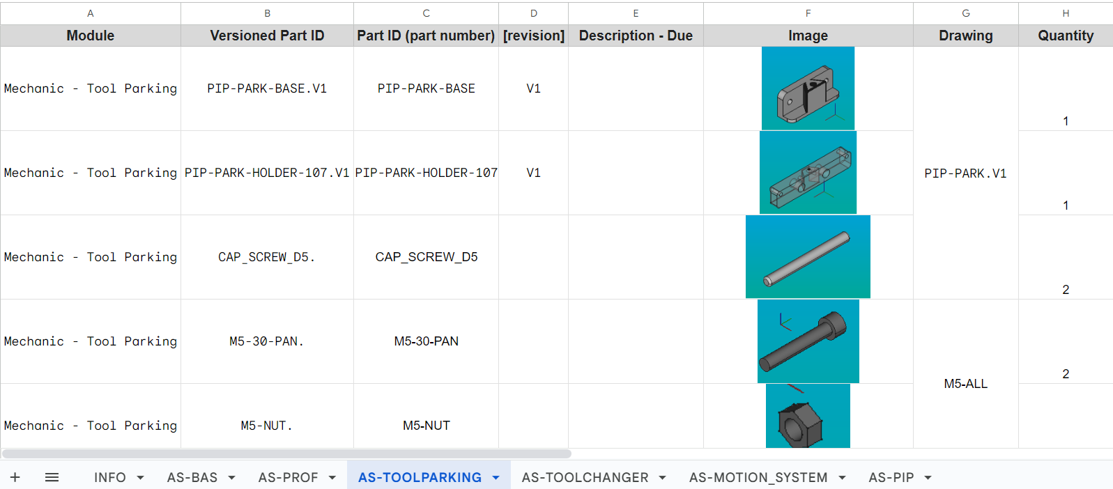
The BOM columns are divided into:
Module: Outlines in which system does that part belong.
Versiones Part ID : Outlines the numer of the piece according to the version of the robot.
Part ID (part number) [revision]: Outlines the part number according to out Part labeling schema.
Description: Brief description of the piece.
Image: Image of the piece.
Drawing: In which drawing does that piece belong.
Quantity: Quantity needed for assembly.
Section views
There are two useful ways to obtain section views:
- In the part workbench, create a a link to an assembly or body you want to cut, and then create a
compoundfrom it. Now use the "section" tool from the Part workbench to create a cross section view (a 2D "sketch" where the cut intersected the parts). - A "true" section view can be generated with the SectionCut tool (image below). Instructions are in the link.