Procedure for CNC Laser Cutting
Cutting with a CNC Laser
This is a short list of notes, full content is due.
Design for laser cutting:
- The laser will remove about of 0.2 mm of acrylic around the intended path during cutting. This means that 0.1 mm of material will be removed from each side of the cut. You can adjust the dimensions of your design to compensate, or check if your laser cutting software can do it for you automatically.
- Example: trying to cut a 4 mm square without compensation will result in a 3.8 mm square (0.1 mm subtracted from each side).
On your PC: DXF export
- Activate the "Part" workbench in FreeCAD.
- Select your body in the model tree, and create a cross-section with the corresponding button in the Part toolbar. A new cross-section object will appear.
- Activate the "TechDraw" workbench in FreeCAD.
- Hide all models except the cross-section.
- Insert a new TechDraw Page.
- Select the cross-section in the object tree, on the sidebar.
- Create a new view. The cross-section should now show up in the TechDraw page.
- Select the TechDraw page on the object tree, and click on the "Export DXF" button. Save the file with an appropriate name, and upload it somewhere accesible.
Warning
Other procedures relying on FreeCAD's DXF exporter can fail to produce useful DXF files. You can try using the direct export starting from the cross-section.
DXF file preview
There are several online and open-source tools for this. For example:
- Vagran's DXF viewer: https://vagran.github.io/dxf-viewer-example/ (source: https://github.com/vagran/dxf-viewer)
- Many others: https://github.com/search?q=dxf%20viewer&type=repositories
On the CNC machine: Preparations
- Turn on the switch on the back.
- On the side panel, flip the red swiches on the left and right (not the center one). They glow red when on. The machin will home itself automatically.
- Connect the CNC machine to the control PC using the USB cable.
- Place the acrylic sheet on the platform.
- Use the controls on the machine to move the laser to the lower left corner of the acrylic sheet (make sure it is at least 5 mm "within" the sheet).
- Press "Focus" and then "Enter".
On the CNC's PC: Load and run the job
- Download the DXF file.
- Open the laser cutting software, and import the DXF file. Check that the origin is on the bottom left (small green rectangle).
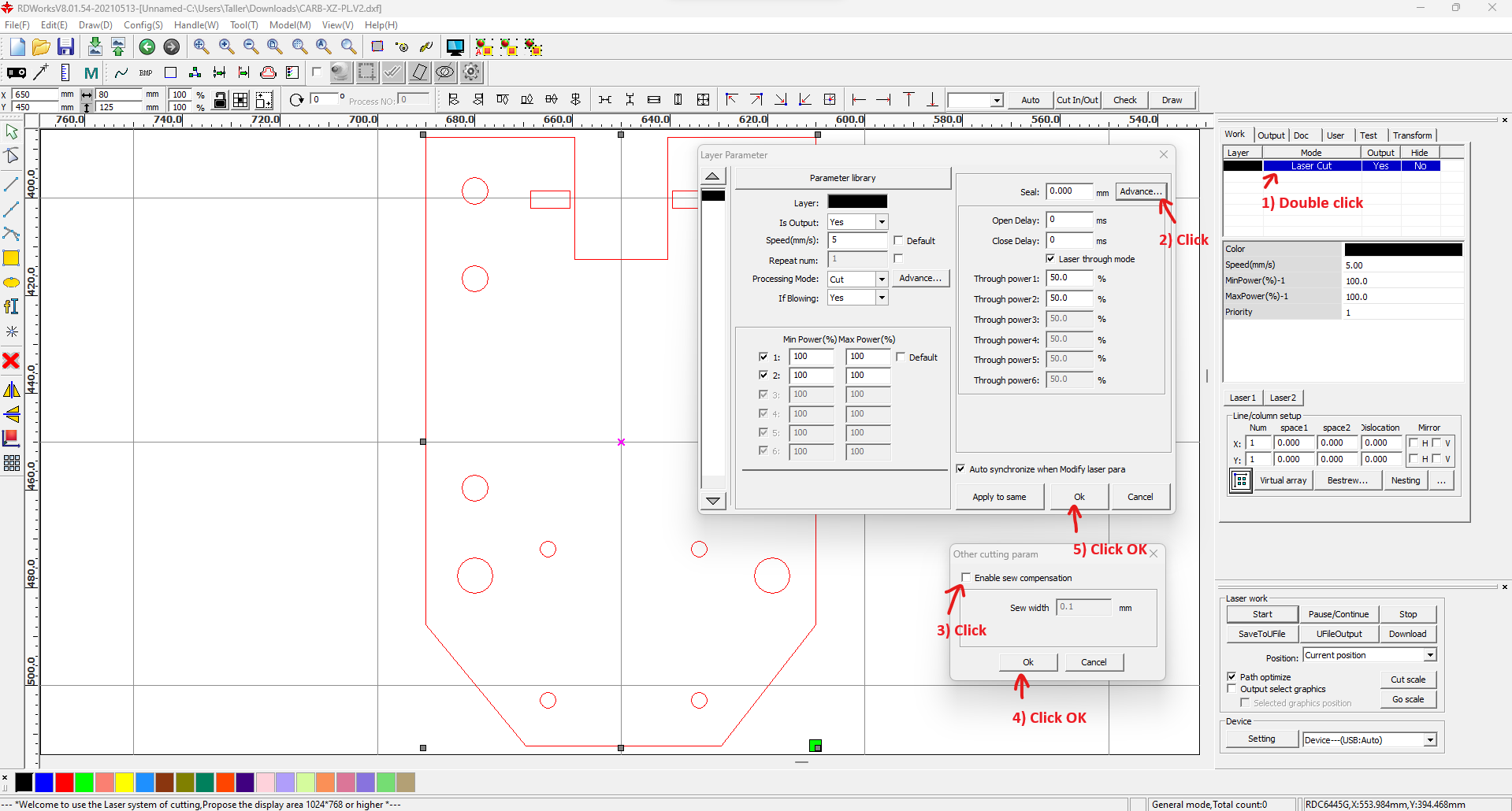
- Adjust the settings (e.g. 5 mm/s cutting speed and 100% power for 8 mm acrylic). Set the appropriate Kerf correction.
- Click on the "simulate button". Check that the internal holes are cut before the external perimeter; otherwise the piece might fall off, or have dimensional inaccuracies.
- Start the cutting job using the "Start" button.
Kerf correction
Because the laser has non-negligible width, the cut will eat away a bit of material through the path.
This causes the cut edges to be slightly offset from the cut path, such that each part has a bit less material than it should. Thus the parts have a sistematic dimensional error equal to the width of the laser beam, and are either smaller (outside cuts, e.g. the outine) or larger (inside cuts e.g. holes) than they should.
We measured this error to be 0.2 mm, meaning that holes were 0.2 mm larger than the should in diameter, and the total width of the piece was 0.2 mm short.
This is called "kerf", and can be corrected using software. The RDWorks software has a setting for this, which we set to 0.1 mm (on either side, which is half of 0.2 mm). You can find more information about this on the internet.
